Coherent photon analog-to-digital conversion device

a conversion device and photon technology, applied in the field of optical information processing technology, can solve the problems of reducing the clock jitter between the accuracy of the photon sampling clock, limiting the accuracy and reducing the clock jitter of the photon sampling clock, so as to improve the sampling precision of the system and improve the coherence

Active Publication Date: 2019-11-07
SHANGHAI JIAO TONG UNIV
View PDF0 Cites 1 Cited by
  • Summary
  • Abstract
  • Description
  • Claims
  • Application Information

AI Technical Summary

Benefits of technology

[0023]2. The phase error information of the sampled signal and the sampling clock source reference output is fed back to the optical clock oscillation source or the sampled signal source to improve the coherence between the optical sampling clock and the sampled signal source, which can break through the theoretical limit of clock jitter and improve the sampling precision of the system.

Problems solved by technology

However, the passive mode-locked laser has a low repetition frequency, and the acquisition of the high-rate photon sampling clock requires more multiplexing channels, which often leads to large structure and more stringent requirement for the precision of channel matching.
However, clock jitter is a significant factor that limits the accuracy of photon sampling.
Therefore, when improving the performance of a photon sampling system, the problem it faces is how to reduce the clock jitter between the photon sampling clock and the sampled signal source.
The system structure is complex and difficult to integrate.
At the same time, the performance and stability of the nonlinear crystal are greatly affected by the environment, which limits the applicable environment of the system.
However, due to the bandwidth limitation of the RF mixer, it cannot be applied to systems with high frequency or high bandwidth, and the system noise is large.
However, although the existing photon sampling techniques and coherent locking techniques have been widely studied, the sampling methods combining the two have not been studied.

Method used


Image

  • Coherent photon analog-to-digital conversion device
  • Coherent photon analog-to-digital conversion device
  • Coherent photon analog-to-digital conversion device

Examples


Embodiment Construction

[0028]In combination with figures and embodiments hereunder, the present invention will be described in detail, but the scope of the present invention is not limited to the embodiments described below.

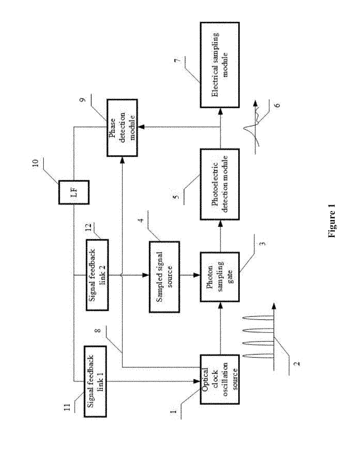
[0029]As shown in FIG. 1, the coherent photon analog-to-digital conversion device of the present invention comprises an optical clock oscillation source 1, a photon sampling gate 3, a sampled signal source 4, a photoelectric detection module 5, an electrical sampling module 7, a phase detection module 9, a loop filter 10, a first signal feedback link 11, and a second signal feedback link 12.

[0030]As shown in FIG. 1, the first output of the optical clock oscillation source 1 is connected with the first input of the photon sampling gate 3; the output of the sampled signal source 4 is connected with the second input of the photon sampling gate 3; the output of the photon sampling gate 3 is connected with the input of the photoelectric detection module 5. The output of the photoelectric de...


PUM

PropertyMeasurementUnit
frequencyaaaaaaaaaa
Radio Frequencyaaaaaaaaaa
speedaaaaaaaaaa

Abstract

A coherent photon analog-to-digital conversion device comprising an optical clock oscillation source, a sampled signal source, a photon sampling gate, a photoelectric detection module, an electrical sampling module, a phase detection module, a loop filter, and signal feedback links. By adjusting the optical clock oscillating source or the sampled signal source, the invention makes the two highly coherent, thereby reducing the clock jitter and greatly improving the sampling precision. It is very important for improving the performance of microwave photon systems that require high time accuracy and high sampling accuracy, such as microwave photon radar and optical communication systems.

Description

CROSS-REFERENCE TO RELATED APPLICATIONS[0001]The subject application is a continuation of PCT / CN2017 / 080975 filed on Apr. 18, 2017, which in turn claims priority on Chinese Application No. CN201710198217.1 filed on Mar. 29, 2017 in China. The contents and subject matter of the PCT international application and the Chinese priority application are incorporated herein by reference.FIELD OF TECHNOLOGY[0002]The invention relates to optical information processing technology, particularly, a coherent photon analog-to-digital conversion device, which realizes high-precision acquisition of radio frequency signals or optical signals.BACKGROUND ART[0003]Photon sampling technology has played an important role in high-speed signal processing and conversion, high-resolution measuring equipment, and optical signal quality testing. At present, high-performance photon sampling technology is at the stage of rapid development. The two major developing trends are ultra-high sampling rate and ultra-hig...

Claims


Application Information

Patent Timeline
Patent Type & Authority Applications(United States)
IPC IPC(8): G02F7/00H04L7/033H01S3/106
CPCH01S3/1068H04L7/0331G02F1/3526G02F7/00H04L7/0075A61B5/1455H03M1/12H03M1/1071A61B5/14551
Inventor ZOU, WEIWENYANG, GUANGYU, LEIQIAN, NACHEN, JIANPING
Owner SHANGHAI JIAO TONG UNIV
Why Eureka
Try Eureka