Automated envelope tracking system

a tracking system and envelope technology, applied in the direction of amplifier types, amplifiers with semiconductor devices/discharge tubes, amplifiers, etc., can solve the problems of high data rate in mobile and wireless communication devices, power amplifier systems may exhibit relatively poor linearity, etc., to reduce cross-path interference degradation or eliminate the effect of different path lengths

Active Publication Date: 2019-11-07
SKYWORKS SOLUTIONS INC
View PDF0 Cites 26 Cited by
  • Summary
  • Abstract
  • Description
  • Claims
  • Application Information

AI Technical Summary

Problems solved by technology

The demand for higher data rates in mobile and wireless communication devices has created technical challenges for power amplifier systems.
Furthermore, certain mobile devices can operate over a wide range of frequencies, including high frequency bands in which power amplifiers may exhibit relatively poor linearity.
The spatial separation of the power amplifiers can cause differences in propagation lengths or delays and in frequency responses of the transmission paths between the single transceiver and the plurality of power amplifiers.
Left uncompensated for, these differences can result in distortions in the amplified RF signal produced, for example, by the clipping effect described above.
This reduced RF signal integrity can degrade communication system performance (for example, by increasing a RF channel's out-of-band emission) and can cause the system to fall short of the requirements imposed by a communication standard.
Furthermore, frequency response and path delays may limit the bandwidth of a conventional envelope tracking system to 40 MHz, as an example.
Although the above description uses a MIMO system to illustrate some technical challenges to the design of envelope tracking systems, at least some of these technical challenges may also occur in Single Input Single Output (SISO) systems.
In other words, regardless of the number of power amplifiers in the system, delay and / or degradation of the RF signal may occur between a transceiver and a power amplifier.
In contrast, many conventional systems are limited to bandwidths of 40 MHz or less for the envelope-tracking signal.
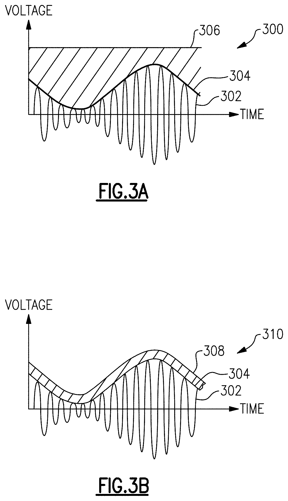
For example, powering a power amplifier using a power amplifier supply voltage that has a magnitude less than that of the RF signal can cause the RF signal to be clipped, thereby creating signal distortion and / or otherwise degrading signal integrity.
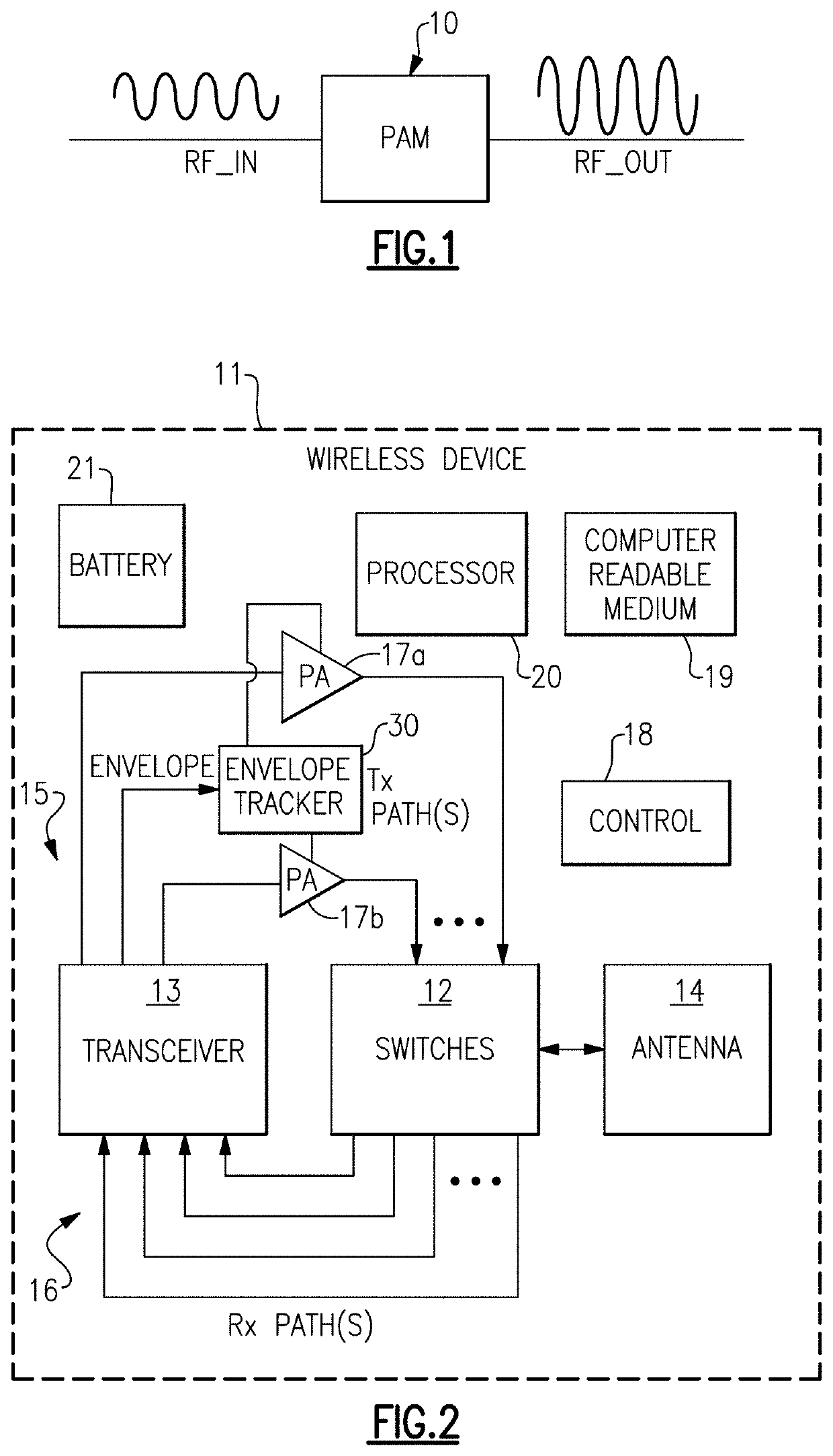
Although providing the clock signal is possible, it is generally not desired because it can create a noise source on the clock signal of the transceiver 13.
The clock signal can generate a high power tone, which may be upconverted and produce noise.
Thus interference produced by the signals may appear to be white noise (e.g., signals with a flat spectral density rather than having discrete spurious components) in the bandwidth of the RF signal.
In contrast, an analog envelope signal may have a similar bandwidth as the RF signal and tends to produce a spurious interference in the RF bandwidth.
The interference becomes more like white noise with increasing sample rate.
Such spurious interference is undesirable in an RF system because, for example, the interference power at the fundamental frequency and the harmonics of the clock may cause degradation to the RF signal.
This interference may cause distortion to the RF input signal because, for example, RF input signals are typically low-power signals.
Furthermore, each FEM may not always transmit in a fixed frequency band.
Although the two signals 1002 and 1004 are not identical in shape, the differences may be attributed to various sources of error in the envelope tracking system, for example magnitude estimation or measurement error.

Method used


Image

  • Automated envelope tracking system
  • Automated envelope tracking system
  • Automated envelope tracking system

Examples


example spectral

Density

[0102]FIG. 11 illustrates a graph 1100 of spectral densities versus frequency. Curve 1102 (thin solid line) is spectral density of an example RF signal amplified through a power amplifier with an ideal envelope tracking supply voltage. Curve 1104 (dotted line) is the spectral density of the same example RF signal amplified through a power amplifier with an envelope tracking signal achievable through a certain embodiment. Line 1106 (thick solid line) shows an example spectral density requirement which may be imposed by a certain communication system or standard. The two spectral densities 1102 and 1104 are not identical in shape. As described above in relation to FIG. 10 above, the differences may be attributed to various sources of error in the envelope tracking system, for example magnitude estimation or measurement error. However, the showing that the achievable spectral density 1104 tracks closely the ideal spectral density 1102 demonstrates that certain embodiments descri...


PUM


Abstract

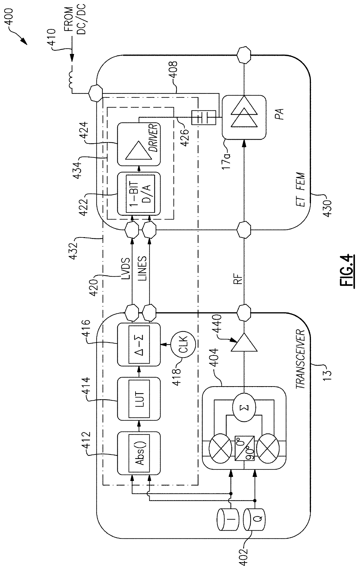
Embodiments described herein relate to an envelope tracking system that uses a single-bit digital signal to encode an analog envelope tracking control signal, or envelope tracking signal for brevity. In certain embodiments, the envelope tracking system can estimate or measure the amplitude of the baseband signal. The envelope tracking system can further estimate the amplitude of the envelope of the RF signal. The system can convert the amplitude of the envelope signal to a single-bit digital signal, typically at a higher, oversample rate. The single-bit digital signal can be transmitted in, for example, a low-voltage differential signaling (LVDS) format, from a transceiver to an envelope tracker. An analog-to-digital converter (ADC or A / D) can convert the single-bit digital signal back to an analog envelope signal. Moreover, a driver can increase the power of the A / D output envelope signal to produce an envelope-tracking supply voltage for a power amplifier.

Description

RELATED APPLICATIONS[0001]This disclosure claims priority to U.S. application Ser. No. 15 / 392,186, which was filed on Dec. 28, 2016 and is titled “AUTOMATED ENVELOPE TRACKING SYSTEM,” the disclosure of which is expressly incorporated by reference herein in its entirety for all purposes, and which claims priority to U.S. Provisional Application No. 62 / 272,958, which was filed on Dec. 30, 2015 and is titled “AUTOMATED ENVELOPE TRACKING SYSTEM,” the disclosure of which is expressly incorporated by reference herein in its entirety for all purposes. Any and all applications, if any, for which a foreign or domestic priority claim is identified in the Application Data Sheet of the present application are hereby incorporated by reference in their entireties under 37 CFR 1.57.BACKGROUNDTechnical Field[0002]This disclosure relates to an automated envelope tracking system.Description of Related Technology[0003]Wireless device manufacturers continue to add new features to wireless devices (e.g....

Claims


Application Information

Patent Timeline
Patent Type & Authority Applications(United States)
IPC IPC(8): H03F1/02H03F3/191H03F3/217H03F3/24H03F1/56
CPCH03F2200/331H03F2200/336H03F3/191H03F1/0227H03F1/565H03F2200/451H03F3/217H03F3/245H03F2200/102
Inventor DROGI, SERGE FRANCOISBALTEANU, FLORINEL G.PANSERI, LUIGICHRISTMAS, CRAIG JOSEPHDICARLO, PAUL T.
Owner SKYWORKS SOLUTIONS INC
Why Eureka
Try Eureka