Multi-stage target cell enrichment using a microfluidic device

a microfluidic device and target cell technology, applied in the field of microfluidic devices, can solve the problems of limiting downstream analysis, increasing the number of contamination of wbcs, and increasing the complexity of clinical samples, so as to achieve dramatic reduction of the number of cells entering the second stag

Active Publication Date: 2019-11-14
BIOLIDICS LTD
View PDF7 Cites 2 Cited by
  • Summary
  • Abstract
  • Description
  • Claims
  • Application Information

AI Technical Summary

Benefits of technology

[0006]The microfluidic device comprises two stages each having a spiral channel portion. After the sample, such as a blood sample, has passed through the 1st stage spiral channel, the bulk of the WBCs are depleted through the first waste outlet, and the total cells entering the second stage are dramatically lowered. This

Problems solved by technology

The challenge is the rarity of CTCs in patient blood sample: CTCs are found in frequencies on the order of 1-10 CTC per mL of whole blood in patients with metastatic disease, while there are several million white blood cells (WBCs), and a billion red blood cells (RBCs) in the same volume of blood.
Although these WBCs are smaller in size, the cells are collected in the CTC channel due to steric interactions caused by the high cellular burden at th

Method used


Image

  • Multi-stage target cell enrichment using a microfluidic device
  • Multi-stage target cell enrichment using a microfluidic device
  • Multi-stage target cell enrichment using a microfluidic device

Examples


Embodiment Construction

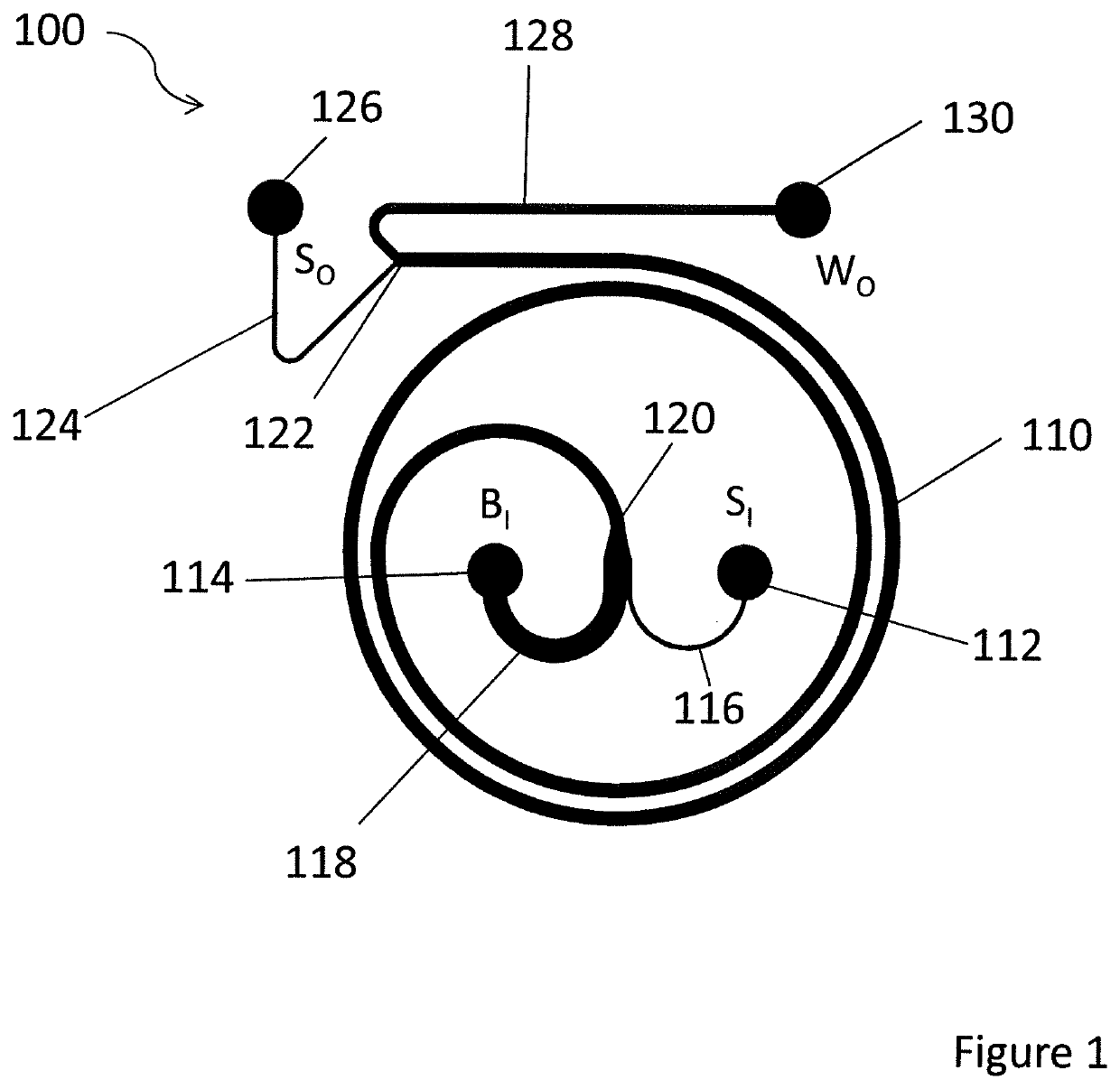
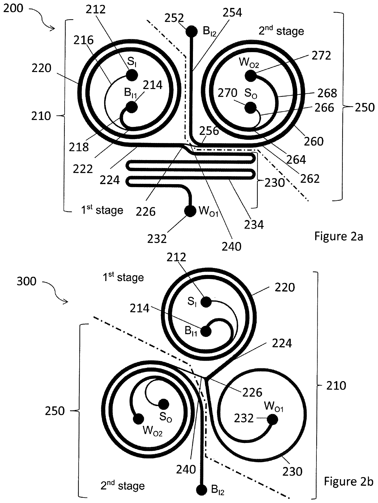
[0022]Embodiments of the present invention relate to microfluidic devices for isolating cells using sized based inertial separation in spiral microchannels. The microfluidic devices may be implemented as a microfluidic chip having a set of microchannels etched or moulded into a material such as glass, silicon or polymer such as Polydimethylsiloxane (PDMS).

[0023]Cells flowing in spiral microchannels are subjected to a combination of inertial lift forces along with the centrifugal acceleration induced Dean drag force. The inertial lift forces, which vary with the fourth power of the cell size, are responsible in focusing the cells at distinct multiple equilibrium positions within the microchannel cross-section. Adding a component of Dean drag, by designing spirally shaped microchannels, these multiple equilibrium positions can be reduced to just one near the inner microchannel wall. As the ratio of lift and Dean drag forces varies for varying cell sizes, the cells can be equilibrated ...


PUM


Abstract

A microfluidic device comprises at least one inlet for receiving a sample comprising target cells and non-target cells; a first spiral channel portion having an upstream end in a central region and a downstream end in a peripheral region, the upstream end being coupled to the inlet, the first spiral channel portion being configured such that the target cells and the non-target cells occupy different streams at the downstream end; a first waste outlet arranged to couple with streams of non-target cells at the downstream end of the first spiral channel portion; a link channel portion arranged to couple with streams of target cells at the downstream end of the first spiral channel portion; a second spiral channel portion having an upstream end in a peripheral region and a downstream end in a central region, the upstream end of the second channel portion being coupled to the link channel portion, the second spiral channel portion being configured such that the target cells and the non-target cells occupy different streams at the downstream end; a second waste outlet arranged to couple with streams of non-target cells at the downstream end of the second spiral channel portion; and a sample outlet arranged to couple with streams of target cells at the downstream end of the second spiral channel portion.

Description

FIELD OF THE INVENTION[0001]Embodiments of the present invention relate to microfluidic devices for enrichment of target cells from blood and other bodily fluids using sized based inertial separation.BACKGROUND[0002]Microfluidic devices such as microfluidics chips typically comprise a set of micro-channels which are etched or molded into a material (for example glass, silicon or polymer such as Polydimethylsiloxane (PDMS)). An application of such microfluidics chips is the enrichment of rare concentrations of relatively large particles / cells from a heterogeneous sample. A typical example is the enrichment of circulating tumor cells (CTCs) from blood cells at very high throughputs. The enrichment of CTCs from patient blood sample is essential for cancer diagnostics and therapy. The challenge is the rarity of CTCs in patient blood sample: CTCs are found in frequencies on the order of 1-10 CTC per mL of whole blood in patients with metastatic disease, while there are several million wh...

Claims


Application Information

Patent Timeline
IPC IPC(8): B01L3/00G01N15/10
CPCB01L2300/088B01L2200/0652G01N2015/1087G01N2015/1081B01L2300/0816B01L2300/0883G01N15/1056B01L3/502761B01L3/00B07C5/12B01D21/26G01N1/28B01L2300/0864
Inventor BHAGAT, ALI ASGAR S.GUAN, GUOFENG
Owner BIOLIDICS LTD
Why Eureka
Try Eureka