
Magnetoresistive sensor with compensating coil

a technology of magnetoresistive sensor and compensating coil, which is applied in the field of magnetic sensors, can solve the problems of large device area of amr sensor, poor space utilization, and high cost, and achieve the effects of small size, improved dynamic range, and reduced cos

Active Publication Date: 2019-11-14
MULTIDIMENSION TECH CO LTD
View PDF3 Cites 4 Cited by
  • Summary
  • Abstract
  • Description
  • Claims
  • Application Information

AI Technical Summary

Benefits of technology

The present invention is a magnetoresistive sensor that has the following technical effects: smaller size, lower cost, increased dynamic range, improved linearity, and decreased hysteresis. The design allows for easy operation in a closed loop mode.

Problems solved by technology

A typical compensating coil (referred to as a bias strip by Honeywell Inc.) is a large serpentine coil placed on top of a sensor chip substrate, which results in poor space utilization, and thus the actual size of the sensor is much larger than the desired size.
However, the AMR sensor has a large device area and high cost.

Method used


Image

  • Magnetoresistive sensor with compensating coil
  • Magnetoresistive sensor with compensating coil
  • Magnetoresistive sensor with compensating coil

Examples


embodiment 1

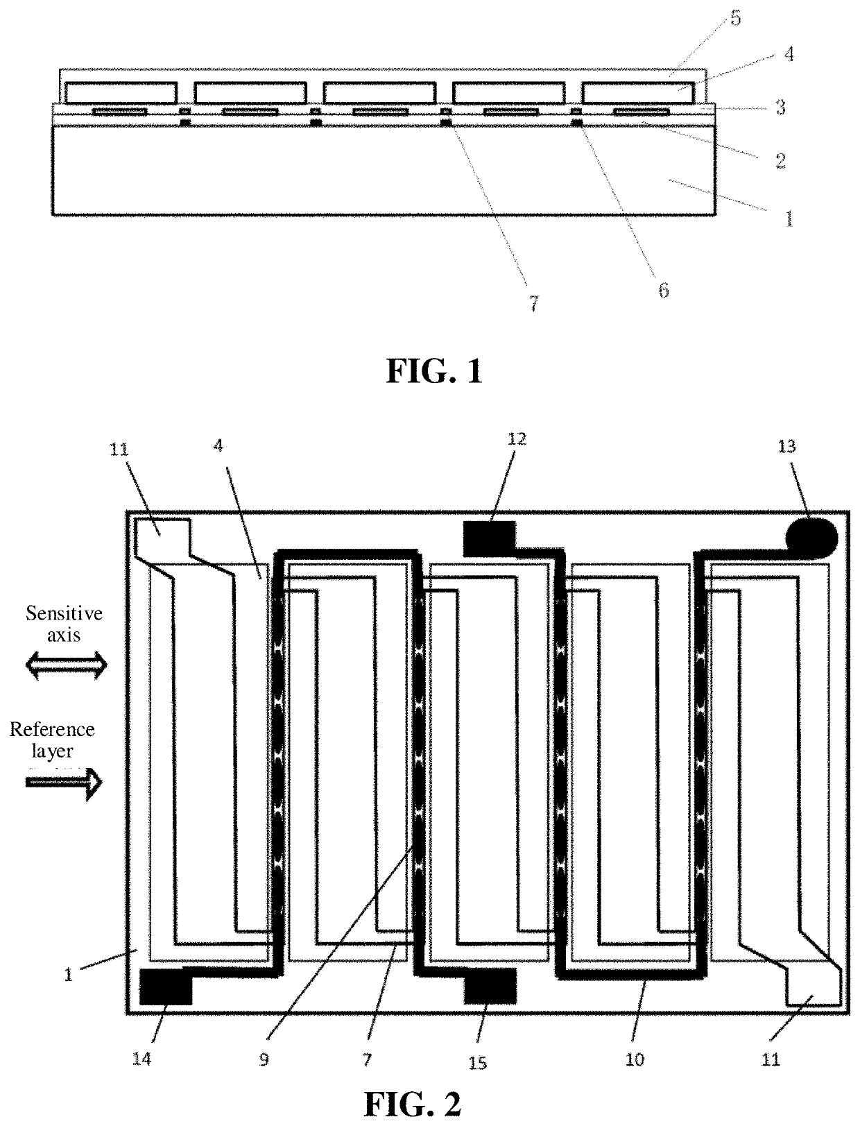
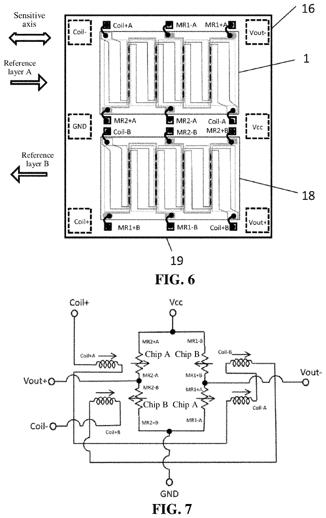
[0034]FIG. 6 is a schematic diagram of an LGA encapsulation of the present invention, wherein 16 represents lead pads on the back of a substrate, and on the back of the magnetoresistive sensor, 17 represents a chip A, and 18 represents a chip B. The chip B is obtained by turning the chip A by 180 degrees. The PCB has an LGA encapsulation form. It can be seen from the figure that a pinning direction of a reference layer of the chip A is from left to right, while a pinning direction of a reference layer of the chip B is opposite to that of the chip A. The chip A and the chip B each consist of a sensor bridge formed by a collection of MR sensor units, a collection of rectangular soft ferromagnetic flux concentrators, and so on. The MR sensor units are interconnected in order to form a push-pull sensor bridge, and the collection of MR sensor units is disposed below the gap between two adjacent soft ferromagnetic flux concentrators.

[0035]FIG. 7 is a schematic circuit diagram of an LGA e...

embodiment 2

[0038]FIG. 9 is a schematic circuit diagram of an LGA encapsulation using a spiral initialization coil of the present invention. As shown in the figure, the chip A and the chip B form a full bridge circuit; a current direction of a compensating coil A disposed above the chip A is the same as that of the chip A, and a current direction of a compensating coil disposed above the chip B is the same as that of the chip B. Magnetic fields generated by the initialization coil and the compensating coil are orthogonal to each other.


PUM


Abstract

A magnetoresistive sensor with a compensating coil comprising a silicon substrate, collection of MR sensor units disposed on the silicon substrate, collection of rectangular soft ferromagnetic flux concentrators, serpentine compensating coil, connecting circuit, and collection of bond pads used for electrical connections. The MR sensor units are interconnected to form a push-pull sensor bridge. The MR sensor units are disposed below the gap between two adjacent soft ferromagnetic flux concentrators. The serpentine compensating coil has a positive current strap over the MR sensor units and a negative current strap under the soft ferromagnetic flux concentrators. The MR sensor bridge and the serpentine compensating coil are connected through bond pads and covered with an encapsulation structure. The magnetoresistive sensor also comprises a spiral initialization coil placed on a substrate within the encapsulating structure. A sensor chip is disposed on the initialization coil, which is used for reducing magnetic hysteresis.

Description

TECHNICAL FIELD[0001]The present invention relates to magnetic sensors, and in particular to a magnetoresistive sensor with a compensating coil.BACKGROUND ART[0002]In many applications, a magnetic sensor needs to be operated in a closed loop to increase the dynamic range, improve the linearity, and decrease the magnetic hysteresis of the sensor. The use of a wafer-level compensating coil allows the magnetic sensor to be easily operated in a closed loop mode.[0003]A typical compensating coil (referred to as a bias strip by Honeywell Inc.) is a large serpentine coil placed on top of a sensor chip substrate, which results in poor space utilization, and thus the actual size of the sensor is much larger than the desired size. An AMR sensor chip from Honeywell Inc. also generates an orthogonal magnetic field by using a bias strip and a reset coil, thereby improving the sensitivity and linearity (a so-called set / reset coil) and providing a capability of operating in a closed loop mode (of ...

Claims


Application Information

Patent Timeline
Patent Type & Authority Applications(United States)
IPC IPC(8): G01R33/00G01R33/09G01R33/022H01L43/08
CPCG01R33/022G01R33/0005H01L43/08G01R33/0011G01R33/095G01R33/091G01R33/0017G01R33/09H10N50/10
Inventor DEAK, JAMES GEZA
Owner MULTIDIMENSION TECH CO LTD
Features
  • Generate Ideas
  • Intellectual Property
  • Life Sciences
  • Materials
  • Tech Scout
  • Unparalleled Data Quality
  • Higher Quality Content
  • 60% Fewer Hallucinations
Learn More