Minimally Invasive Ultrasonic Osteotome Head and Minimally Invasive Ultrasonic Bone Power System

a technology of ultrasonic osteotome and bone power system, which is applied in the field of medical instruments, can solve the problems of inability to achieve the maximum efficiency of ultrasonic osteotome, inability to bend the osteotome head laterally in the transforaminal endoscope, and limited operating space, so as to reduce the risk of medical complications, no damage, and precise cutting

Active Publication Date: 2019-11-28
BEIJING SMTP TECH CO LTD
View PDF0 Cites 2 Cited by
  • Summary
  • Abstract
  • Description
  • Claims
  • Application Information

AI Technical Summary

Benefits of technology

[0021]The present disclosure replaces a high-speed grinding drill with an ultrasonic bone power system, thus reducing the medical risk, providing more precise cutting, having no damage to soft tissues such as blood vessels and nerves, and providing better hemostasis.
[0022]In the present disclosure, the head end of the minimally invasive ultrasonic osteotome head bends laterally at an angle, and bending the head end can remove bone tissues around the transforaminal endoscope, so that the operator has as much operating space as possible under a limited channel of the transforaminal endoscope, thereby improving the bone removal efficiency. Further, providing knurled or skewed teeth in the bending portion provides better grinding or cutting for the bone tissues around the transforaminal endoscope.
[0023]By configuring the osteotome rod of the minimally invasive ultrasonic osteotome head as two detachable portions, the present disclosure also solves the problem that the bending osteotome head cannot pass through the channel of the transforaminal endoscope and thus the osteotome rod cannot be fitted into the endoscope channel, thereby further facilitating assembly of the osteotome head.

Problems solved by technology

Due to the rotating operation mode, the grinding drill is easy to scrape soft tissue during an operation to cause a wire drawing effect, and is easy to cause a blind view due to blood such that a medical person will have an unclear vision, which might further cause medical accidents.
When an ultrasonic osteotome head system is inserted into the transforaminal endoscope, due to the limitation of the ultrasound, the osteotome head cannot be bent laterally in the transforaminal endoscope.
Therefore, the operating space is very limited, and the operation could be carried out only in a direction of the transforaminal endoscope, such that the bone tissues around the transforaminal endoscope cannot be removed, thus impossible to achieve the maximum efficiency of the ultrasonic osteotome.

Method used


Image

  • Minimally Invasive Ultrasonic Osteotome Head and Minimally Invasive Ultrasonic Bone Power System
  • Minimally Invasive Ultrasonic Osteotome Head and Minimally Invasive Ultrasonic Bone Power System
  • Minimally Invasive Ultrasonic Osteotome Head and Minimally Invasive Ultrasonic Bone Power System

Examples


embodiment 1

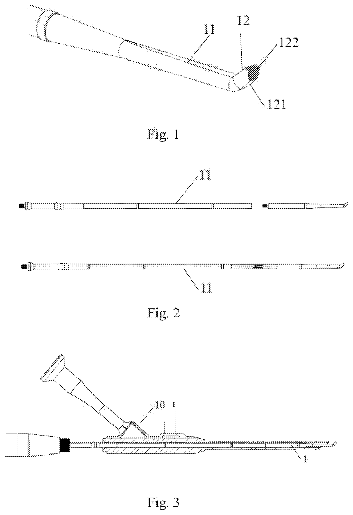
[0035]As shown in FIG. 1, the embodiment discloses a minimally invasive ultrasonic osteotome head 1, which comprises an osteotome rod 11 and a head end 12, the head end 12 being located at a front end of the osteotome rod 11 and bending laterally at a certain angle. A bottom surface 121 of the bending portion is a square arc surface, and upper and lower inclined surfaces of a transverse surface 122 of the bending portion are provided with knurled teeth.

[0036]In the assembly procedure, since the bending head end cannot pass through the channel of the transforaminal endoscope, in order to enable the minimally invasive ultrasonic osteotome head 1 to operate together with the transforaminal endoscope, as shown in FIG. 2, the osteotome rod 11 of the minimally invasive ultrasonic osteotome head is configured as two portions, a front portion connected with the head end 12 and a rear portion connected with an ultrasonic handle. The two portions are connected by means of threads by which the...

embodiment 2

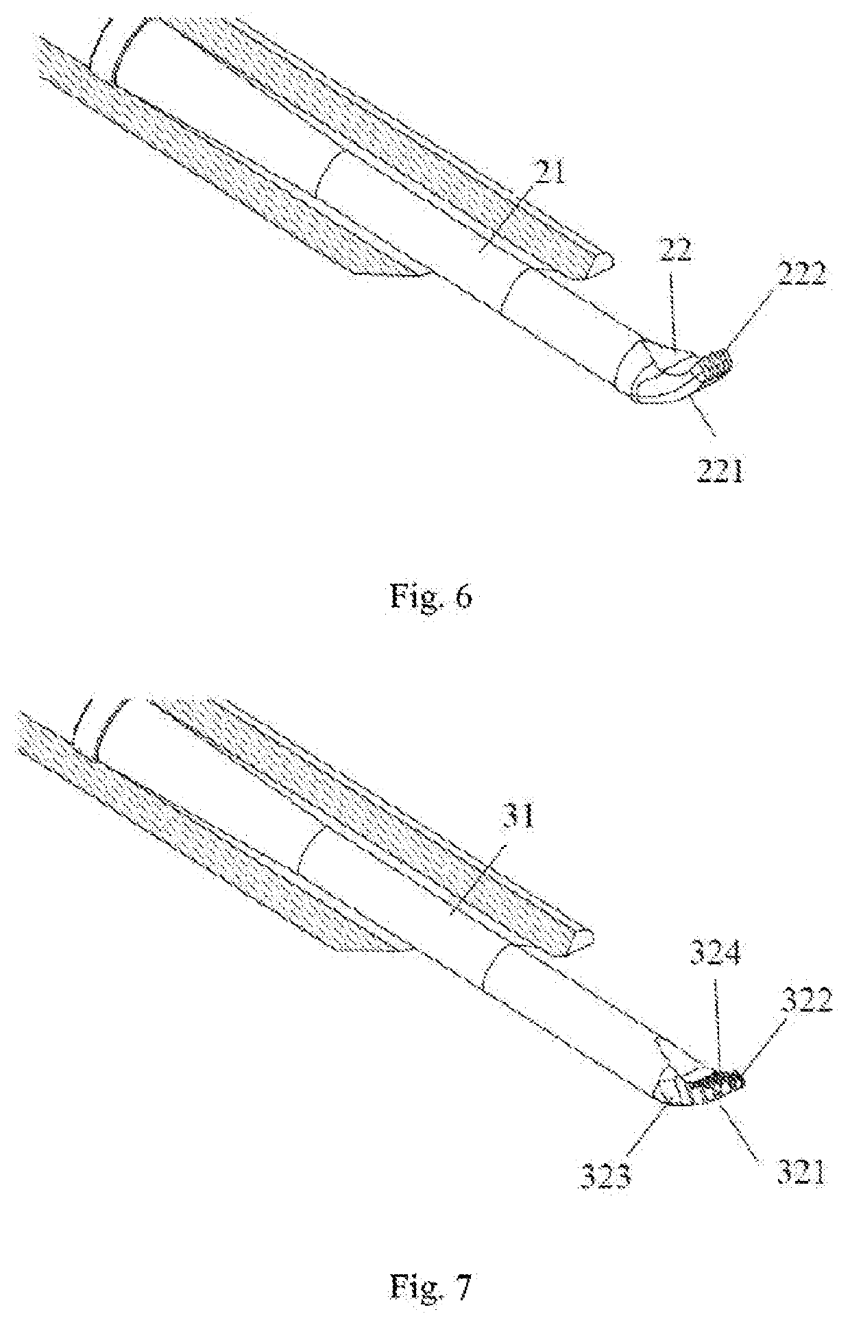
[0040]FIG. 6 shows a minimally invasive ultrasonic osteotome head 2 of Embodiment 2 of the present disclosure. The osteotome head 2 comprises an osteotome rod 21 and a head end 22, the head end 22 being located at a front end of the osteotome rod 21 and bending laterally at a certain angle. The head end 22 is of a rake-shape, and a transverse surface 222 of the bending portion is provided with skewed teeth.

[0041]Similar to Embodiment 1, in order to facilitate assembly, the osteotome rod 21 is also configured as two portions, a front portion connected to the head end 22 and a rear portion connected to the handle, the two portions being connected by means of threads. The osteotome rod 21 may be of a hollow structure through the entire rod to discharge water for perfusion directly at the head end; or only part of the osteotome rod is of a hollow structure, so that water is discharged through side holes in the middle of the rod.

[0042]The minimally invasive ultrasonic osteotome head 2 ma...

embodiment 3

[0043]FIG. 7 is a minimally invasive ultrasonic osteotome head 3 of Embodiment 3 of the present disclosure. The osteotome head 3 comprises an osteotome rod 31 and a head end 32, the head end 32 being located at a front end of the osteotome rod 31 and bending laterally at a certain angle. The head end 32 is spoon-shaped, and a top surface 324 of the bending portion is provided with knurled teeth. Further, a transverse surface 322 and a side surface 323 of the bending portion could be provided with skewed teeth.

[0044]Similar to Embodiment 1, in order to facilitate assembly, the osteotome rod 31 is also configured as two portions, a front portion connected to the head end 32 and a rear portion connected to the handle, the two portions being connected by means of threads. The osteotome rod 31 may be of a hollow structure through the entire rod to discharge water for perfusion directly at the head end; or only part of the osteotome rod is of a hollow structure, so that water is discharge...


PUM


Abstract

A minimally invasive ultrasonic cutter head and a minimally invasive ultrasonic powered system for bone; the minimally invasive ultrasonic cutter head comprises an cutter rod (11, 21, 31, 41, 51, 61) and a head end (12, 22, 32, 42, 52, 62), the head end (12, 22, 32, 42, 52, 62) being located at a front end of the cutter rod (11, 21, 31, 41, 51, 61), and the head end (12, 22, 32, 42, 52, 62) being bent laterally at a certain angle, wherein knurled teeth or skewed teeth are provided on the bent portion. By means of bending the head end (12, 22, 32, 42, 52, 62), bone tissue around the intervertebral foramen may be removed. Therefore, a surgeon may, as much as possible, have more operation space under the limited foramen channel, thereby increasing bone removal efficiency.

Description

TECHNICAL FIELD[0001]The present disclosure relates to the technical field of medical instruments and, in particular, to a minimally invasive ultrasonic osteotome head and a minimally invasive ultrasonic bone power system.BACKGROUND[0002]With the development of modern medical technology, minimally invasive surgery under a transforaminal endoscope has been widely applied to the clinical orthopedic surgery. The existing power tool under a transforaminal endoscope is mainly a high-speed grinding drill that removes bone tissues by high-speed rotation of a grinding drill head. Due to the rotating operation mode, the grinding drill is easy to scrape soft tissue during an operation to cause a wire drawing effect, and is easy to cause a blind view due to blood such that a medical person will have an unclear vision, which might further cause medical accidents.[0003]An ultrasonic bone power system is a power tool using ultrasonic energy to perform an operation, and has outstanding characteris...

Claims


Application Information

Patent Timeline
Patent Type & Authority Applications(United States)
IPC IPC(8): A61B17/32A61B17/16A61B34/00
CPCA61B17/32002A61B2017/320084A61B2017/00473A61B2017/00119A61B2017/320064A61B17/1626A61B2017/0034A61B17/1659A61B17/320068A61B34/25A61B2017/320072A61B2017/00477A61B2217/007A61B17/1671A61B17/1644A61B17/1703A61B2017/320078A61B2017/320075A61B2017/00973
Inventor CAOLI, ZHENZHOUZHAN, SONGTAO
Owner BEIJING SMTP TECH CO LTD
Why Eureka
Try Eureka