
Synchronization and Broadcast Signal Design for 5G

a broadcast signal and synchronization technology, applied in the field of wireless communication methods, can solve the problems of huge technical challenges, extremely low latency and high reliability services, and significant challenges to the current wireless system, and achieve the effects of significant capacity, power consumption, spectral efficiency and interference improvemen

Active Publication Date: 2019-11-28
FUJITSU LTD
View PDF0 Cites 11 Cited by
  • Summary
  • Abstract
  • Description
  • Claims
  • Application Information

AI Technical Summary

Benefits of technology

The present invention is about improving the efficiency of radio beamforming transmissions from base stations in cellular systems. This can lead to better performance in terms of capacity, power consumption, and spectral efficiency, as well as reduced interference.

Problems solved by technology

Nowadays mobile access to the Internet or other communications networks is becoming a crucial necessity for both business and personal life and there are significant challenges to the current wireless systems due to the popularity of new applications such as social networking, cloud based services and big data analysis.
(iii) extremely low latency and high reliability services.
The technical challenges for designing such a sophisticated and complicated system are tremendous and significant breakthroughs will be required both on the network side and in the radio interface.
These challenges are the large path loss, poor penetration / scattering properties and possible non-existing line of light path.
Theoretically, the difference between them is that, at a particular time instance, analog beamforming builds a single beam using many of antennas, to cover a limited area with smaller power consumption and hardware usage; whereas digital beamforming can have multiple beams simultaneously to cover a relatively wide area with more power consumption and more hardware cost.
We also generally assume that a given TRP is associated with a particular cell, but this limitation may not apply in all systems.
On the other hand using a beam purely for PSS / SSS / PBCH purposes is not efficient.
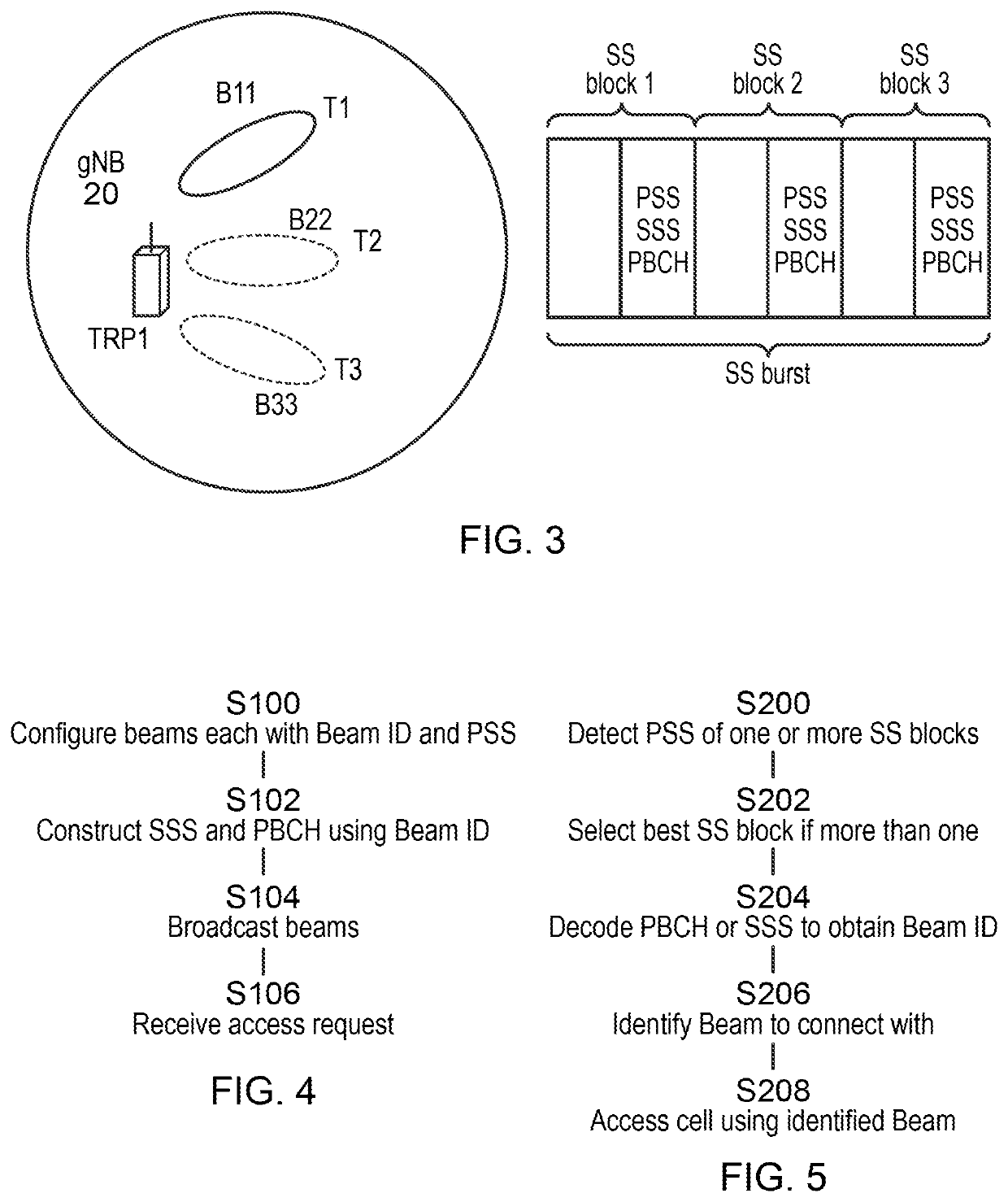
In practice the scenario could be much more complicated; for example the number of beams used within each individual SS burst may vary (configured by the network), or the duration of a beam may be longer than that of a SS block.
Compared with LTE, one new issue for NR is that it is preferable for a terminal to identify a beam during initial access.
Note that having one cell per beam and simply expanding the total number of cell IDs to be indicated by PSS / SSS from that in LTE may not be feasible, since this would lead to blind detection of a very large number of different sequences.
Consequently, a problem exists of how to deliver this beam ID, bearing in mind the operation of PSS, SSS and PBCH.

Method used


Image

  • Synchronization and Broadcast Signal Design for 5G
  • Synchronization and Broadcast Signal Design for 5G
  • Synchronization and Broadcast Signal Design for 5G

Examples


first embodiment

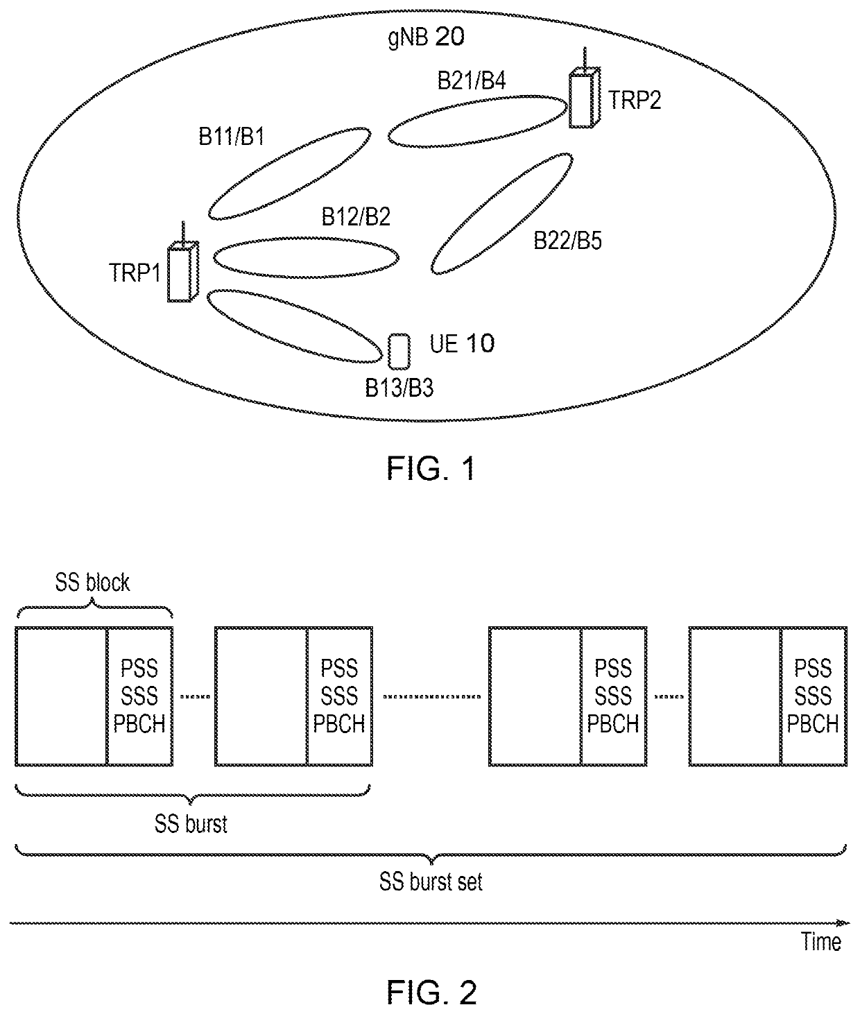
[0119]Based on the assumption that an identical PBCH is transmitted by each beam, a first embodiment is to use SSS to transmit the beam ID. As variations of this embodiment the beam ID may be constructed in different ways, for example:—[0120](a) A unique beam ID is defined for each beam provided by a gNB, independent of the cell. For example in FIG. 1 the beams from TRP 1 are numbered B1, B2 and B3 and those from TRP2 continue the same numbering sequence as B4 and B5.[0121](b) A beam ID is composed of its cell identity plus its beam identity within the cell. For example in FIG. 1 the second beam from TRP1 may be expressed as Bc2 where c is the cell ID. In the case a subset of the unique beams available in the system may be associated with a particular cell (or vice versa).[0122](c) A beam ID is composed of its TRP identity plus its beam identity within this TRP. For example in FIG. 1 the second beam from TRP1 may be expressed as B12 where in beam ID Bxy, x represents the number of T...

second embodiment

[0133]As already mentioned, conventionally, in LTE a UE needs its cell ID to deduce the location of the reference symbols embedded in the PBCH signal. A UE will further use the cell ID to decode these reference symbols, and then it can further decode the PBCH signal. A second embodiment of the present invention, which may be an extension of the first embodiment, employs special, cell ID independent, or partially cell ID independent, reference signals, and the PBCH signal is decoded based on these reference signals. Then a UE can decode PBCH signal without the knowledge (or full knowledge) of the cell ID, although the cell ID could still be transmitted on every beam. In this way, cell ID decoding can be decoupled from PBCH decoding in order to provide more design flexibility and ensure forward compatibility.

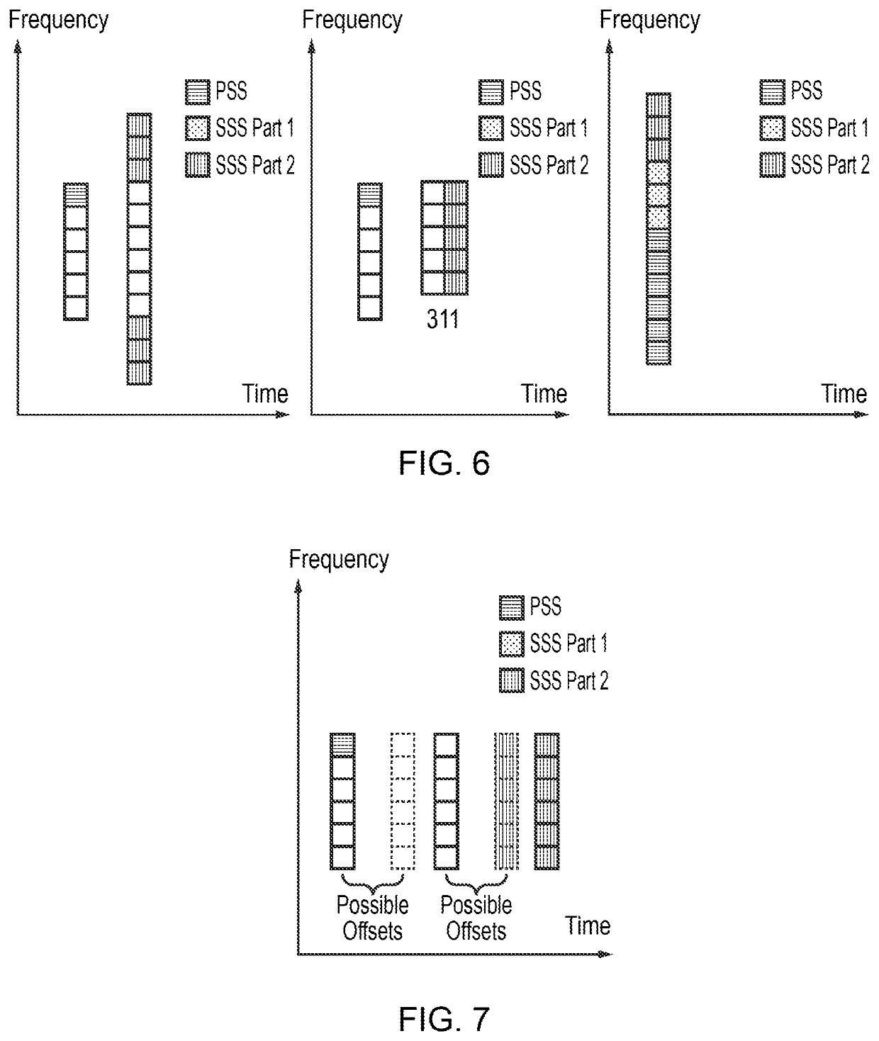
[0134]To implement this embodiment, one solution is to introduce special demodulation reference signals (which we denote here as “PBCH DM RS”) for PBCH decoding. With this solutio...

third embodiment

[0141]The third embodiment is to transmit beam ID by using PBCH. This is primarily envisaged as an alternative to the first embodiment, although it might be possible to combine both embodiments for providing beam ID redundantly (e.g. providing a cross-check of correct reception), or to use the different embodiments to transmit different parts of a beam ID. It was agreed in the above mentioned 3GPP RAN1 87 meeting report, Reno, USA 14th-18th November, USA that the NR PBCH is a non-scheduled broadcast channel carrying at least a part of minimum system information with fixed payload size and periodicity predefined in the specification depending on carrier frequency range. However what information can be classified as minimum system information is still under investigation. A concrete implementation is to include beam ID information in the PBCH information. In LTE the MIB, which is the message transmitted by PBCH, consists of 24 bits where there are 10 spare bits for future use. Using a...


PUM


Abstract

A method in a 5G wireless communication system to transmit a beam ID or part of a beam ID by joint design of a secondary synchronization sequence (SSS) and Physical Broadcast Channel (PBCH). In 5G during the initial access procedure a terminal (10) will try to obtain fundamental system information / identifiers which are required for future signal transmission / reception activities. Due to the extensive usage of beamforming techniques in 5G, besides identifying a cell ID and obtaining time / frequency synchronization, the terminal (10) may be required to identify a beam ID during the initial access procedure. Therefore, a beam ID is transmitted as part of synchronization signals (SS) broadcast by a gNB (20), more particularly as part of SSS or as part of PBCH. The synchronization signals may be transmitted as a set of SS blocks, each having an index, which may be a time index, for facilitating identification.

Description

CROSS REFERENCES TO RELATED APPLICATIONS[0001]This application is a continuation application of International Patent Application No. PCT / EP2018 / 051761, filed Jan. 24, 2018, and claims priority to European Patent Application No. EP17160353.3 filed Mar. 10, 2017 the contents of each are herein wholly incorporated by reference.FIELD OF THE INVENTION[0002]The present invention relates to a wireless communication method in which terminals connect to cells in a wireless network. The present invention further relates to a wireless communication system, a transmission point, a station (e.g. terminal) and a wireless communication system.[0003]Particularly, but not exclusively, the present invention relates to techniques for designing synchronization signals and broadcast channels in a “5G” wireless communication system.BACKGROUND OF THE INVENTION[0004]Wireless communication systems are widely known in which terminals (also called user equipments or UEs, subscriber or mobile stations) communi...

Claims


Application Information

Patent Timeline
IPC IPC(8): H04W56/00H04W72/04H04W48/10H04W76/11
CPCH04W76/11H04W56/001H04W72/0446H04W72/046H04W48/10H04W48/16
Inventor WEI, XUSHENGMOULSLEY, TIMOTHY
Owner FUJITSU LTD
Learn More