Equipment and methods for automated sample processing for diagnostic purposes

Pending Publication Date: 2019-12-05
YANTAI AUSBIO LAB
View PDF0 Cites 3 Cited by
  • Summary
  • Abstract
  • Description
  • Claims
  • Application Information

AI Technical Summary

Benefits of technology

[0024]In a first embodiment, the upper section has an inner diameter larger than an inner diameter of the lower section and the upper section has an outer diameter larger than an outer diameter of the lower section. The intermediate section is located between the upper section of the tube and the lower section, wherein a top of the intermediate section connects to a bottom of the upper section and a bottom of the intermediate section connects to a top of the lower section. An inner diameter and an outer diameter of the intermediate section decreases from the top to the bottom of the intermediate section of the tube. The tube exhibits a plurality of fastening means for fixing the tube in a tube rack. The plurality of fastening means is located on an outer surface of the intermediate section and the lower section. The fastening means thus guarantee

Problems solved by technology

Erroneous results in identifying infected samples may be life-threatening for literally everyone exposed to the source of the sample or the samples of the source.
However, in recent times there has been little advancement which was broadly applicable for routine clinical analysis at a reasonable cost and performance, and there are still many cases of pathogen detection failures every day.
Typically, during latent phase or at an early phase of infection, it may not be possible to detect targeted serological markers in plasma because the analytes are not yet being released from the infected cells or the traces of analytes are beyond limit of detection (LOD).
Plasma or serum as conventional targeted sample is apparently insufficient to establish a comprehensive and complete analysis that covers the entire pathogen lifecycle.
However, current routine clinical practices are yet unable to fully incorporate cellular analysis for both economical and practical reasons.
Commercial p

Method used


Image

  • Equipment and methods for automated sample processing for diagnostic purposes
  • Equipment and methods for automated sample processing for diagnostic purposes
  • Equipment and methods for automated sample processing for diagnostic purposes

Examples


Embodiment Construction

[0070]In the following, preferred embodiments of the invention are described with reference to the figures, in which:

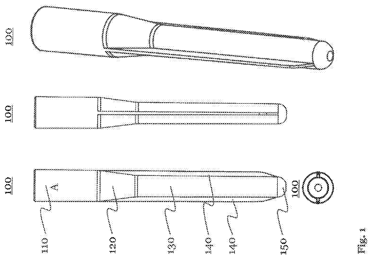
[0071]FIG. 1 shows various views of a tube illustrating geometrical features of the tube according to an exemplary embodiment of the invention.

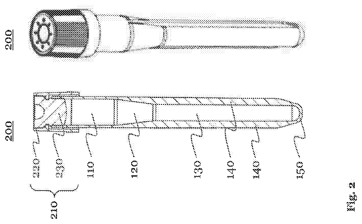
[0072]FIG. 2 shows further views of the tube including a tube cap according to an exemplary embodiment of the invention.

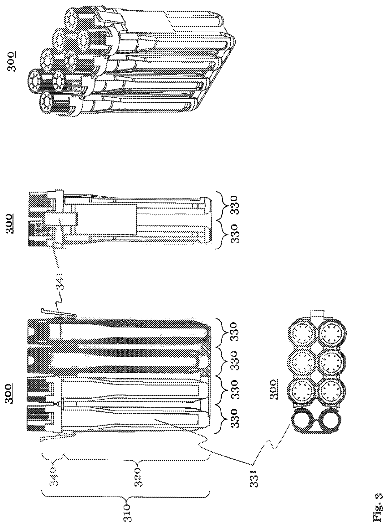
[0073]FIG. 3 shows various views of a tube rack including tubes and tube caps, according to an exemplary embodiment of the invention.

[0074]FIG. 4 shows an enlarged section of a longitudinal cut in a three-dimensional view of a part of the tube rack equipped with a tube and a tube cap, according to an exemplary embodiment of the invention.

[0075]FIG. 5 illustrates an exemplary embodiment according to the invention of a first step of the method for automated sample processing, in which a tube rack including tubes and tube caps is transferred, from a tray full of tube racks (left part of the figure) to a support l...


PUM


Abstract

A tube for sample collection and sample processing in a tube rack includes an upper section, an intermediate section, and a lower section. The intermediate section connects the upper section and the lower section of the tube, and an inner diameter of the intermediate section can decrease from top to bottom. A fastening means can fix the tube in a tube rack. The tube can include a pierceable tube cap sealing the tube, and the tube rack can be configured such that the tube may be pulled off the tube cap by a centrifugation force. The tube can include a volume of density gradient medium covered by a separating gel to enhance sample separation.

Description

FIELD OF THE INVENTION[0001]The invention relates to the field of automated sample processing for diagnostics purposes. More particularly, the present invention is directed to enhanced and coherently designed equipment and methods to allow for automated sample processing for diagnostic purposes to enhance both sample throughput and diagnostic precision.BACKGROUND OF THE INVENTION[0002]One of the key focus of reagent developers and diagnostic instrument manufacturers is reliability, sensitivity and specificity of tests. Early detection is an important counter-measure to mitigate the various risks associated with an infection. Erroneous results in identifying infected samples may be life-threatening for literally everyone exposed to the source of the sample or the samples of the source. Blood donors, laboratory personnel and blood recipients may be mentioned as examples.[0003]Therefore, sample screening reagents are continuously improved and advanced screening technologies are further...

Claims


Application Information

Patent Timeline
IPC IPC(8): B01L3/00B01L9/06G01N35/00
CPCB01L3/5021G01N2035/00495B01L2300/042B04B5/0421B01L2300/044B01L9/06B04B2005/0435G01N35/0099B01L2300/021B01L2300/0832B01L2300/022B01L2200/025
Inventor WANG, ZHAOQIANG
Owner YANTAI AUSBIO LAB
Why Eureka
Try Eureka