Battery system

a battery system and battery technology, applied in the field of battery systems, can solve the problems of insufficient charging, and insufficient static control of battery power output, so as to achieve the effect of effectively avoiding overcharging of the first subset of battery cells

Active Publication Date: 2019-12-05
SAMSUNG SDI CO LTD
View PDF0 Cites 5 Cited by
  • Summary
  • Abstract
  • Description
  • Claims
  • Application Information

AI Technical Summary

Benefits of technology

[0015]The battery system according to embodiments of the present invention provides a dual power supply (e.g., a redundant power supply) for the control unit of the battery system. Thus, the control unit is reliably (e.g., always) supplied with a fraction of the total voltage of all of the battery cells of the battery system, and thus, under- and overvoltage with respect to the control electronics in the control unit is avoided. For example, the control unit is either supplied with the voltage of the first subset of battery cells via the first diode and the output node, or the control unit is supplied with the output voltage of the step-down converter (e.g., the stepped down voltage of all of the plurality of battery cells) via the output node. Hence, the battery system according to embodiments of the present invention provides a dual (or redundant) power supply for the electronics of the control unit as an integrated feature of the battery system.
[0016]The battery system according to embodiments of the present invention provides a cost-optimized approach for the electric supply of the electronics as a separate buck converter chip may be omitted between a high voltage domain of the battery system (e.g., all of the battery cells of the battery system) and the control unit. Further, the step-down converter of the battery system is configured to be switched off when the control unit is in a sleep mode, and the step-down converter does not provide an output voltage to the output node when the control unit is in the sleep mode. Hence, the sleep current (or standby current) of the battery system is reduced because the step-down converter is not operated permanently because the control unit is redundantly supplied via the first subset of battery cells. Further, a bleed out (e.g., a current leak) of the first subset is avoided by supplying the control unit via the step-down converter at least during active states of the control unit. Also, unwanted charging or overcharging of the first subset is avoided by the first diode.
[0020]In some embodiments, the SBC may include an internal buck converter and may be safely supplied with an operation voltage between about 6 V and about 41 V. Hence, the step-down converter of the battery system may provide the SBC with a rather high output voltage while the SBC provides overvoltage protection to the BMU and also to additional control units.
[0022]In another embodiment, the battery system may further include a charging path that is connected in parallel with the first diode and that includes a second switch. For example, the charging path circumvents the first diode and allows for an electric current to flow from the output node to the intermediate node according to the second switch's switching state. By controlling the second switch, the output voltage of the step-down converter may be utilized for active balancing (e.g., active cell balancing) of the battery system. When the second switch is set to a non-conductive state, the output voltage of the step-down converter supplies (e.g., solely supplies) the control unit (according to the potential at the output node), but when the second switch is set to a conductive state, the output voltage of the step-down converter charges the first subset of battery cells (according to the potential at the output node). The battery system according to embodiments of the present invention thereby allows for integrated balancing between the first subset and the second subset of battery cells. Hence, eventual charging losses of the first subset of battery cells due to supplying the control unit when the control unit is in a sleep mode may be evened out once the control unit is activated.
[0023]In one embodiment, the charging path may further include a constant current source that is interconnected between the cathode of the first diode and the second switch. Instead of the constant current source, a current limiter may be used. Hence, overcharging of the first subset of battery cells may be effectively avoided. In some embodiments, the second switch is a PNP transistor, with the emitter of the PNP transistor being connected to the cathode of the first diode and the collector of the PNP transistor being connected to the anode of the first diode. In such an embodiment, the current limiter is realized in that a basis of the PNP transistor is connected to the emitter of the PNP transistor via a resistor network as well as to a collector of an additional NPN transistor, an an emitter of the NPN transistor is connected to the first node. By controlling the basis of the NPN transistor, the second switch is realized, while the both transistors and the resistor network together function as the current limiter. For example, the control unit controls the signal applied to the basis or gate of the NPN transistor and controls the second switch.

Problems solved by technology

To meet the dynamic power demands of various electrical consumers connected to the battery system, a static control of battery power output and charging is often insufficient.
This approach is disadvantageous as security related functions of the battery system should be guaranteed at all times, and because the 12 V board system is drained even during non-active phases of the vehicle, a self-supplied battery system is desired.
Further, the step-down converter of the battery system is configured to be switched off when the control unit is in a sleep mode, and the step-down converter does not provide an output voltage to the output node when the control unit is in the sleep mode.
Hence, eventual charging losses of the first subset of battery cells due to supplying the control unit when the control unit is in a sleep mode may be evened out once the control unit is activated.

Method used


Image

  • Battery system
  • Battery system
  • Battery system

Examples


first embodiment

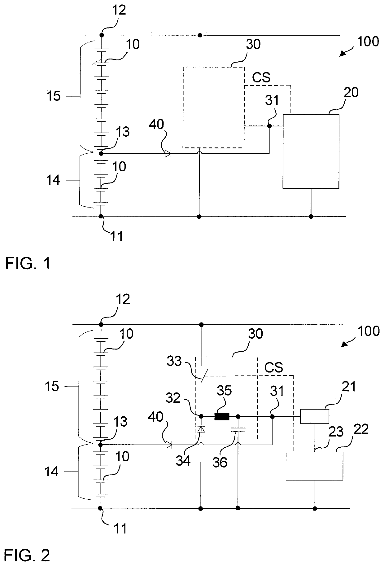
[0044]FIG. 1 schematically illustrates a battery system 100 according to the present invention. The battery system 100 includes a plurality of battery cells (e.g., twelve battery cells) 10 that are connected to each other in series between a first node 11 and a second node 12. Each battery cell 10 provides a voltage of about 4 V so that a voltage of about 48 V is applied between the first node 11 and the second node 12. The stack of battery cells 10 further includes an intermediate node 13 that divides the cell stack into a first subset 14 of battery cells 10 and a second subset 15 of battery cells 10. Therein, four battery cells 10 are disposed between the first node 11 and the intermediate node 13, and eight battery cells 10 are disposed between the intermediate node 13 and the second node 12, but the present invention is not limited thereto. Hence, in the illustrated embodiment, a voltage of about 16 V is applied between the first node 11 and the intermediate node 13, and a volta...

second embodiment

[0047]FIG. 2 schematically illustrates a battery system 100 according to the present invention. In FIG. 2, the same reference signs as those used in FIG. 1 refer to the same or substantially similar components as describe above with respect to FIG. 1 and a repeated description thereof may be omitted.

[0048]In the battery system 100 shown in FIG. 2, the step-down converter 30 is a buck converter 30 that includes a third node 32 and a first switch 33 interconnected between the second node 12 and the third node 32. The buck converter 30 further includes a second diode 34. The anode of the second diode 34 is connected to the first node 11, and the cathode of the second diode 34 is connected to the third node 32. The buck converter 30 further includes an inductor 35 interconnected between the third node 32 and the output node 31 and a capacitor 36 interconnected between the inductor 35 and the first node 11 and in parallel with the second diode 34.

[0049]The control unit shown in FIG. 2 in...

third embodiment

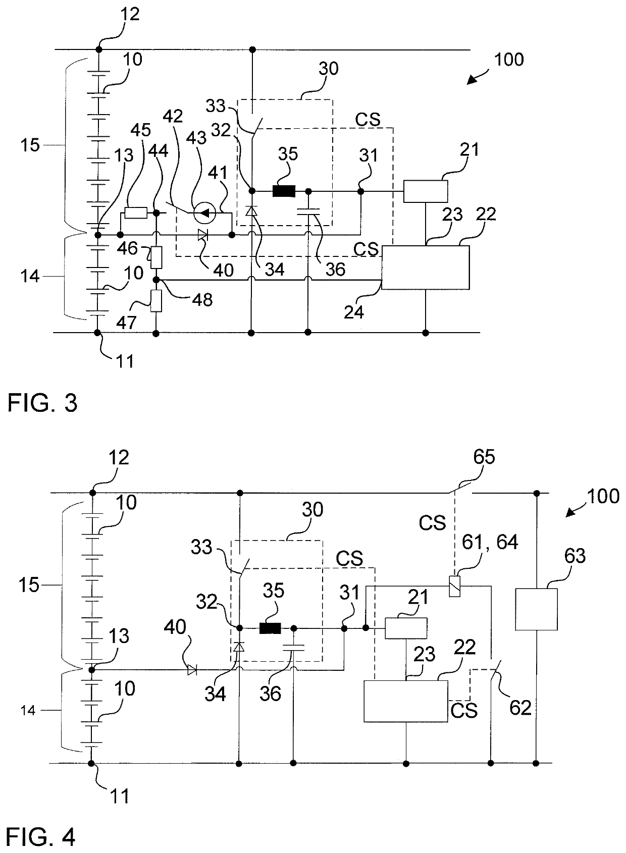
[0051]FIG. 3 schematically illustrates a battery system 100 according to the present invention. In FIG. 3, the same reference signs as those used in FIGS. 1 and 2 refer to the same or substantially similar components, and a repeated description thereof may be omitted.

[0052]The battery system 100 shown in FIG. 3 further includes a charging path 41 connected in parallel with the first diode 40. The charging path 41 includes a constant current source 43 and a second switch 42. The constant current source 43 is connected to the cathode of the first diode 40, and the second switch 42 is connected to the anode of the first diode 40. The BMU 22 shown in FIG. 3 is further configured to control the second switch 42 by outputting another control signal CS to the second switch 42. The charging path 41 allows for the charging of the first subset 14 of battery cells 10 by the output voltage of the buck converter 30 via the output node 31.

[0053]When the first switch 33 is set into the non-conduct...


PUM

PropertyMeasurementUnit
voltageaaaaaaaaaa
voltageaaaaaaaaaa
voltageaaaaaaaaaa

Abstract

A battery system includes: a plurality of battery cells electrically connected to each other in series between a first node and a second node; an intermediate node dividing the plurality of battery cells into a first subset of battery cells and a second subset of battery cells; a step-down converter connected in parallel with the plurality of battery cells between the first node and the second node and having an output node; a first diode, an anode of which is connected to the intermediate node and a cathode of which is connected to the output node; and a control unit interconnected between the output node and the first node and configured to control the step-down converter.

Description

CROSS-REFERENCE TO RELATED APPLICATION[0001]This application claims priority to and the benefit of Korean Patent Application No. 10-2019-0050857, filed in the Korean Intellectual Property Office on Apr. 30, 2019, and European Patent Application No. 18175438.3, filed in the European Patent Office on Jun. 1, 2018, the entire contents of which are incorporated herein by reference.BACKGROUND1. Field[0002]Aspects of embodiments of the present invention relate to a battery system including an integrated redundant power supply for a control unit.2. Description of the Related Art[0003]A rechargeable (or secondary) battery differs from a primary battery in that it is designed to be repeatedly charged and discharged, while the latter is designed to provide only an irreversible conversion of chemical to electrical energy. Low-capacity rechargeable batteries are used as power supplies for small electronic devices, such as cellular phones, notebook computers, and camcorders, while high-capacity ...

Claims


Application Information

Patent Timeline
Patent Type & Authority Applications(United States)
IPC IPC(8): H02J7/00H01M2/10H02J7/02H01M50/204H01M50/289
CPCH01M2/1016H02J7/0083H02J7/022H01M10/425H02J2207/10H02J2207/20H02J7/0031H02J7/0063H02J2310/48Y02E60/10H02J7/00308H02J7/00302H02J7/00712H02J7/007182H02J7/00711H01M50/204H01M50/289H02J7/00718H02J7/02
Inventor HOFER, MAXIMILIANDOCZY, STEFANHAINDL, MICHAELRICHTER, GERALDWEISSENSTEINER, BIRGITKURCIK, PETERMARCHL, MANFRED
Owner SAMSUNG SDI CO LTD
Why Eureka
Try Eureka