Programmable Railcar Tank Cleaning System

a technology for cleaning systems and railcars, applied in cleaning processes and equipment, tank wagons, chemistry apparatus and processes, etc., can solve the problems of dust and vapors, potential danger to those using water nozzles, and dust and vapors, so as to achieve the effect of moving the nozzle assembly

Active Publication Date: 2019-12-12
AGI ENG INC
View PDF0 Cites 6 Cited by
  • Summary
  • Abstract
  • Description
  • Claims
  • Application Information

AI Technical Summary

Benefits of technology

[0021]A controller takes this data and outputs the command signals to corresponding servo valves or servo-proportional valves; therefore, synchronizing the multiple axes and effectively moving the nozzle assembly along the desired path. The controller will also sequence events as needed.

Problems solved by technology

Railcar tanks used for storage can be cleaned using handheld water nozzles, which is slow, tedious, and inefficient along with having potential danger to those using the water nozzles.
Personnel working in these environments would be exposed to hazardous and potentially flammable fluids, dusts and vapors in addition to strenuous conditions due to the requirement of the use of protective gear.
Also, this work mostly performed in confined spaces making it cumbersome to use the requisite handheld blast equipment.
Handheld blast nozzles produce high velocities and high thrust forces that an operator must counteract.
This leads to fatigue and injury.
More sophisticated, remotely controlled systems have been employed but are limited due to visibility.
Since the area is dangerous and inaccessible by humans, remotely operated cameras are required.
Remotely operated cameras also slow, tedious, and inefficient to use as this only provides a limited viewing area in a dark tank, with limited light, making it difficult for cameras to capture images with adequate detail and contrast.
Additionally, mist and airborne particles common in waste storage tanks can obstruct the camera view and render it useless.
More challenging is how an operator is required to visually survey the area to determine the appropriate cleaning pattern given the limited visibility of the camera.
Once the stream passes the outlet, a secondary operation must be implemented to properly capture the waste increasing operation costs and the overall time to effectively clean a tank.

Method used


Image

  • Programmable Railcar Tank Cleaning System
  • Programmable Railcar Tank Cleaning System
  • Programmable Railcar Tank Cleaning System

Examples


Embodiment Construction

[0045]Before explaining the disclosed embodiments of the present invention in detail it is to be understood that the invention is not limited in its applications to the details of the particular arrangements shown since the invention is capable of other embodiments. Also, the terminology used herein is for the purpose of description and not of limitation.

[0046]In the Summary above and in the Detailed Description of Preferred Embodiments and in the accompanying drawings, reference is made to particular features (including method steps) of the invention. It is to be understood that the disclosure of the invention in this specification does not include all possible combinations of such particular features. For example, where a particular feature is disclosed in the context of a particular aspect or embodiment of the invention, that feature can also be used, to the extent possible, in combination with and / or in the context of other particular aspects and embodiments of the invention, an...


PUM


Abstract

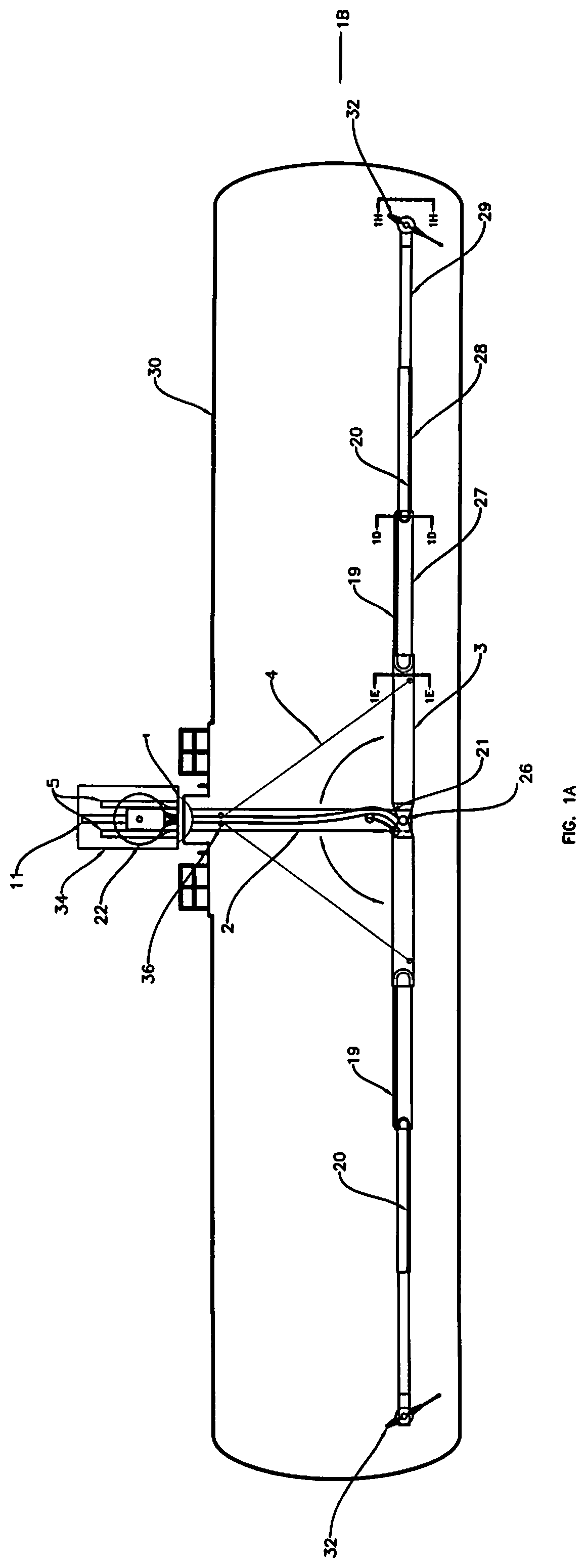
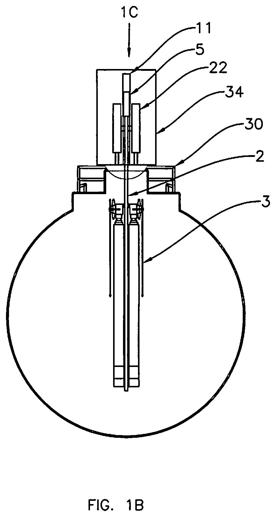
Systems, devices, and methods for passing railcar tank cleaning systems through the opening and mounted to existing manways. The invention can extend horizontally more than 25 feet and clean rail cars up to and beyond approximately 102 inches in diameter for manual, automated, or semi-automated programmable railcar tank cleaning systems, devices and methods for providing safe and efficient methods for breaking up oil, tar, chemical, radioactive, hazardous, or any other liquid, solid, or sludge waste inside rail tank cars and the like with nozzles which utilize fluid jets to break up, liquefy, and motivate tank material. The programmable railcar cleaning system can be a standalone, independent unit or integrated into new designs and/or existing systems. Simplified programming and user interface allow an operator to remotely operate the system. The various capabilities of this invention allow cleaning in a quicker and more efficient manner. The system is hydraulically controlled and can work in the presence of flammable vapors and dust.

Description

CROSS REFERENCE TO RELATED APPLICATIONS[0001]This application claims the benefit of priority to U.S. Provisional Application Ser. No. 62 / 683,215 filed Jun. 11, 2018, and this application claims the benefit of priority to U.S. Provisional Patent Application 62 / 784,512 filed Dec. 23, 2018. The entire disclosure of each of the applications listed in this paragraph are incorporated herein by specific reference thereto.FIELD OF INVENTION[0002]This invention relates to breaking up oil and tar, or any other chemical, or hazardous liquid, solid, or sludge waste from inside railcar tank and the like, and more specifically, to manual, automated, or semi-automated, tank cleaning devices, systems and methods for breaking up oil and tar, or any other chemical, radioactive or hazardous liquid, solid, or sludge waste from inside railcar tanks and the like, with nozzles which utilize fluid jets to break up, liquefy, and motivate tank material. The invention can work with tanks having high temperatu...

Claims


Application Information

Patent Timeline
Patent Type & Authority Applications(United States)
IPC IPC(8): B08B9/46B61K11/00B08B9/08
CPCB08B2209/08B61K11/00B08B9/46B08B9/0813B61D5/00B08B9/0936B60S3/008B05B13/0636B05B3/028
Inventor INNES, ALEX G.
Owner AGI ENG INC
Why Eureka
Try Eureka