Multifunctional spacer for knee surgery to achieve balanced resection

a multi-functional spacer and knee technology, applied in the field of multi-functional spacers for knee surgery to achieve balanced, can solve the problems of poor joint performance, patient discomfort, inconvenient operation, etc., and achieve the effect of reducing inventory and costs

Active Publication Date: 2019-12-19
MCMINN DEREK JAMES WALLACE +1
View PDF0 Cites 1 Cited by
  • Summary
  • Abstract
  • Description
  • Claims
  • Application Information

AI Technical Summary

Benefits of technology

[0039]A fourth aspect of the invention relates to use of multifunctional spacers according to the first aspect of the invention, during knee surgery, wherein the posterior portion of a first spacer is inserted between a trial tibial component and a medial femoral condyle and a posterior portion of a second spacer is inserted between the trial tibial component an...

Problems solved by technology

Mal-alignment of the cutting guide in either of these capacities will lead to incorrect location of the femoral component.
This may lead to patient discomfort and poor performance of the joint.
If the cutting guide is located too far in the posterior direction, the cuts will result in a divot or notch in the femur, which may lead to supracondylar fracture of the femur.
Furthermore, if the cutting guide, and therefore the femoral component, is rotationally mal-aligned, the collateral ligaments may not be under the correct tension.
If these ligaments and structures are not under equal tension the patient will have a feeling of instability and there is an increased risk that the bearing parts of the TKR will dislocate.
Such distraction devices are usually employed in spinal surgery and are large, heavy and cumbersome devices.
Since they are operated independently there is a risk that the collateral ligaments and soft tissue structures on the medial and lateral sides of the knee will be unequally tensioned.
In addition, these distraction devices require a significant amount of effort by the surgeon to operate since they generally involve lever-operated crank mechanisms.
Furthermore, it is not uncommon for such devices to hinder access to the knee, during an operation...

Method used


Image

  • Multifunctional spacer for knee surgery to achieve balanced resection
  • Multifunctional spacer for knee surgery to achieve balanced resection
  • Multifunctional spacer for knee surgery to achieve balanced resection

Examples


Embodiment Construction

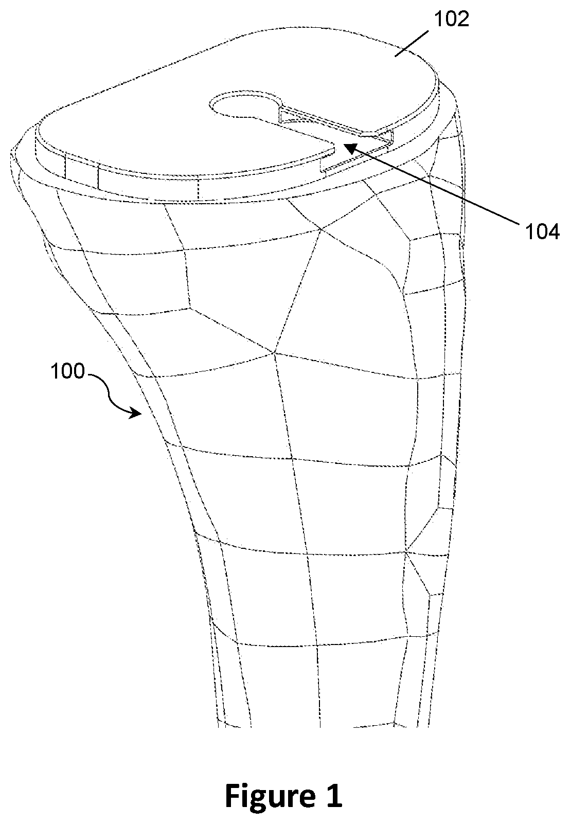
[0057]FIG. 1 shows a first step in a total knee replacement procedure, in accordance with embodiments of the invention. Notably, a surgeon may utilise tools such as those described above and in GB2445620B without significantly altering his / her surgical technique.

[0058]As shown in FIG. 1, a proximal arthritic surface of a tibia 100 has been resected and fitted with a trial tibial component in the form of a trial tibial baseplate 102. The resection may be performed using an extra-medullary guide, an intramedullary guide, a custom tibial cutting guide, a navigation-assisted tibial cutting guide or a robot-assisted tibial cutting guide. Known knee-specific surgical instruments are used to prepare the proximal surface of the tibia 100 before the trial tibial baseplate 102 is inserted. In this particular embodiment, the trial tibial baseplate 102 is similar to that described in GB2445620B but further includes a radial anterior slot 104 which is configured for receipt of an alignment arm a...


PUM


Abstract

A multifunctional spacer for knee surgery is described comprising a main body configured for use with a single femoral condyle and having an anterior portion of a first height and a posterior portion of a second height, wherein the second height is greater than, equal to or less than the first height. In addition, the anterior portion and/or the posterior portion is provided with an attachment mechanism for selective attachment of a height adjuster.

Description

FIELD OF THE INVENTION[0001]The present invention relates to a multifunctional spacer for knee surgery to achieve balanced resection. Particularly, but not exclusively, the invention relates to a multifunctional spacer for use in total knee replacement (TKR) operations.BACKGROUND[0002]The Applicant's earlier patent, GB2445620B, describes instrumentation for use in knee surgery, upon which the present invention builds. The content of GB2445620B is therefore incorporated by reference into the present disclosure.[0003]Prosthetic knee replacement surgery is employed to replace damaged or diseased parts of the knee. A particularly common disease that affects joints such as the knee is osteoarthritis. This disease usually increases in severity with age and leads to a high demand for successful knee replacement operations.[0004]So-called total knee replacement (TKR) surgery involves replacing the ends of the femur and tibia with prosthetic femoral and tibial components. In some cases, the ...

Claims


Application Information

Patent Timeline
IPC IPC(8): A61B17/17A61F2/46A61F2/38
CPCA61F2/389A61B2017/0268A61F2/461A61F2002/4658A61F2002/30616A61F2002/4615A61B17/1764A61F2/4684A61B17/155A61B17/025A61B17/154
Inventor MCMINN, DEREK JAMES WALLACE
Owner MCMINN DEREK JAMES WALLACE
Why Eureka
Try Eureka