Supercharge Your Innovation With Domain-Expert AI Agents!

Cryogenic Cooling System

a cooling system and cryogenic technology, applied in the field of cryogenic cooling systems, can solve the problems of limiting the overall efficiency of the cooling process, limiting the use of heat pipes, and unable to achieve the effect of reducing the cost of cooling, and achieving high switching ratio, excellent performance, and high effective thermal conductivity

Active Publication Date: 2019-12-19
OXFORD INSTR NANOTECH TOOLS
View PDF0 Cites 8 Cited by
  • Summary
  • Abstract
  • Description
  • Claims
  • Application Information

AI Technical Summary

Benefits of technology

The invention relates to a system for cooling a target assembly using a heat switch and heat pipe. The heat switch is designed to efficiently cool the target assembly by short-circuiting the thermal gradient across the heat switch assembly. The heat pipe is also used to cool the second cooled stage, which helps to reduce the overall cool down time of the system. Heat radiation shields are used to isolate the target assembly from higher temperature stages and the ambient environment. The gas gap heat switches are designed to have high effective thermal conductivity and low thermal conductivity at cryogenic temperatures. The reduced cool down time is particularly useful for systems with a high thermal mass. The heat transfer across the heat pipe stops when the coolant freezes in the heat pipe. The "technical effects" of this invention include improved cooling efficiency and reduced cool down time for the system.

Problems solved by technology

The sole use of one or more gas gap heat switches to thermally couple the second cooled stage and the target assembly does not enable sufficiently rapid cool down of the target assembly.
However, when multiple gas gap heat switches are provided, a temperature gradient is required across each switch to promote heat flow, thereby limiting the overall efficiency of the cool down process.
Similarly the sole use of a heat pipe is not sufficiently effective.
Their operational range is limited however: making them unsuitable for cooling the target assembly from room temperature to the temperature of the second cooled stage.

Method used


Image

  • Cryogenic Cooling System
  • Cryogenic Cooling System
  • Cryogenic Cooling System

Examples


Embodiment Construction

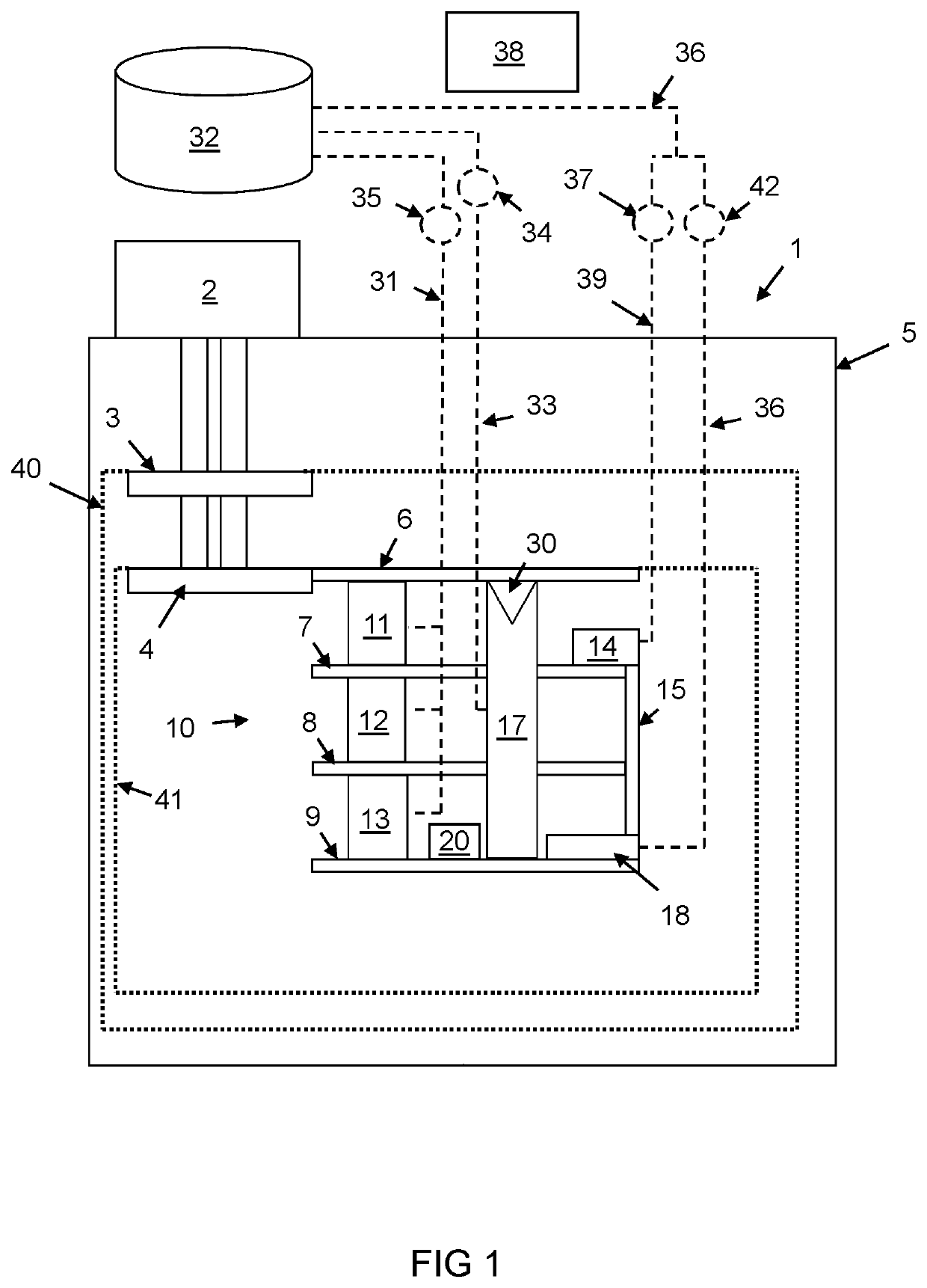
[0050]A first embodiment of a cryogenic cooling system will now described. With reference to FIG. 1, there is illustrated a sectional view of the interior of a cryogen-free cooling system the main part of which is a cryostat 1. Cryostats are well known in the art and are used to provide low temperature environments for various apparatus. The cryostat 1 is typically evacuated when in use, this being to improve the thermal performance by the removal of convective and conductive heat paths through any gas within the cryostat. The cryostat 1 in the present example is a cryogen-free cryostat in that it does not contain a reservoir of liquid helium, the cooling of the cryostat instead being achieved by use of conductive cooling from a mechanical refrigerator. However, despite the “cryogen-free” term, some coolant (in this case helium) is typically present within the cryostat when in use, including in the liquid phase.

[0051]The main cooling power of the cryostat 1 is provided by a mechanic...


PUM


Abstract

A cryogenic cooling system is provided comprising: a mechanical refrigerator, a heat pipe and a heat switch assembly. The mechanical refrigerator has a first cooled stage and a second cooled stage. The heat pipe has a first part coupled thermally to the second cooled stage and a second part coupled thermally to a target assembly. The heat pipe is adapted to contain a condensable gaseous coolant when in use. The heat switch assembly comprises one or more gas gap heat switches, a first end coupled thermally to the second cooled stage and a second end coupled thermally to the target assembly. The cryogenic cooling system is adapted to be operated in a heat pipe cooling mode in which the temperature of the second cooled stage is lower than the first cooled stage and wherein the temperature of the target assembly causes the coolant within the second part of the heat pipe to be gaseous and the temperature of the second cooled stage causes the coolant in the first part of the heat pipe to condense. The target assembly is cooled by the movement of the condensed liquid coolant from the first part of the heat pipe to the second part of the heat pipe during the heat pipe cooling mode. The cryogenic cooling system is further adapted to be operated in a gas gap cooling mode in which the temperature of the second cooled stage causes freezing of the coolant. The heat switch assembly is adapted to provide cooling from the second cooled stage to the target assembly during the gas gap cooling mode via the one or more gas gap heat switches.

Description

FIELD OF THE INVENTION[0001]The present invention relates to a cryogenic cooling system and a method for operating this system.BACKGROUND TO THE INVENTION[0002]There are a number of technological applications which require cooling to low temperatures and in particular cryogenic temperatures, which may be thought of as those below 100 kelvin. Liquid helium-4 is often used as a cryogenic coolant due to its boiling point at atmospheric pressure of around 4 kelvin. Superconducting magnets and other experimental devices are traditionally cooled to around 4 kelvin using liquid cryogens, these including nitrogen and helium. The relatively large enthalpy content of these cryogens in either liquid or gaseous form ensures a rapid cooling from room temperature down to that of the cryogen in question. Despite the widespread use and success of liquid cryogens, the apparatus necessary to handle such low temperature liquids is often rather bulky, complicated and expensive. Furthermore, the relativ...

Claims


Application Information

Patent Timeline
Patent Type & Authority Applications(United States)
IPC IPC(8): F25B9/02F25B9/10F25B9/14F25B49/02F25D19/00G05D23/00
CPCF25B2309/021F25B9/02F25B49/022F25D19/006F25B9/10F25B9/145F28F2013/008G05D23/00F25B25/005F25B23/006F25B2400/17F25B2500/26F28D2021/0033F28D15/025F25B9/12F28D15/02H01H37/00
Inventor MATTHEWS, ANTHONYPATTON, MARK
Owner OXFORD INSTR NANOTECH TOOLS
Features
  • R&D
  • Intellectual Property
  • Life Sciences
  • Materials
  • Tech Scout
  • Unparalleled Data Quality
  • Higher Quality Content
  • 60% Fewer Hallucinations
Learn More