PTC Heater with Reduced Switch-On Current

a switch-on current and heater technology, applied in the direction of resistor details, ohmic-resistance heating, positive temperature coefficient thermistors, etc., can solve the problem of low thermal resistance of the heater, achieve the effect of reducing the dependence of the quality of the heater on the variation of parameters during production, reducing the switch-on current, and increasing the breakdown voltag

Pending Publication Date: 2019-12-19
EPCOS AG
View PDF2 Cites 1 Cited by
  • Summary
  • Abstract
  • Description
  • Claims
  • Application Information

AI Technical Summary

Benefits of technology

[0006]Embodiments provide PTC heaters in which the switch-on current is reduced, the breakdown voltage is increas

Problems solved by technology

The thermal resistance of the heater is low

Method used


Image

  • PTC Heater with Reduced Switch-On Current
  • PTC Heater with Reduced Switch-On Current
  • PTC Heater with Reduced Switch-On Current

Examples


Embodiment Construction

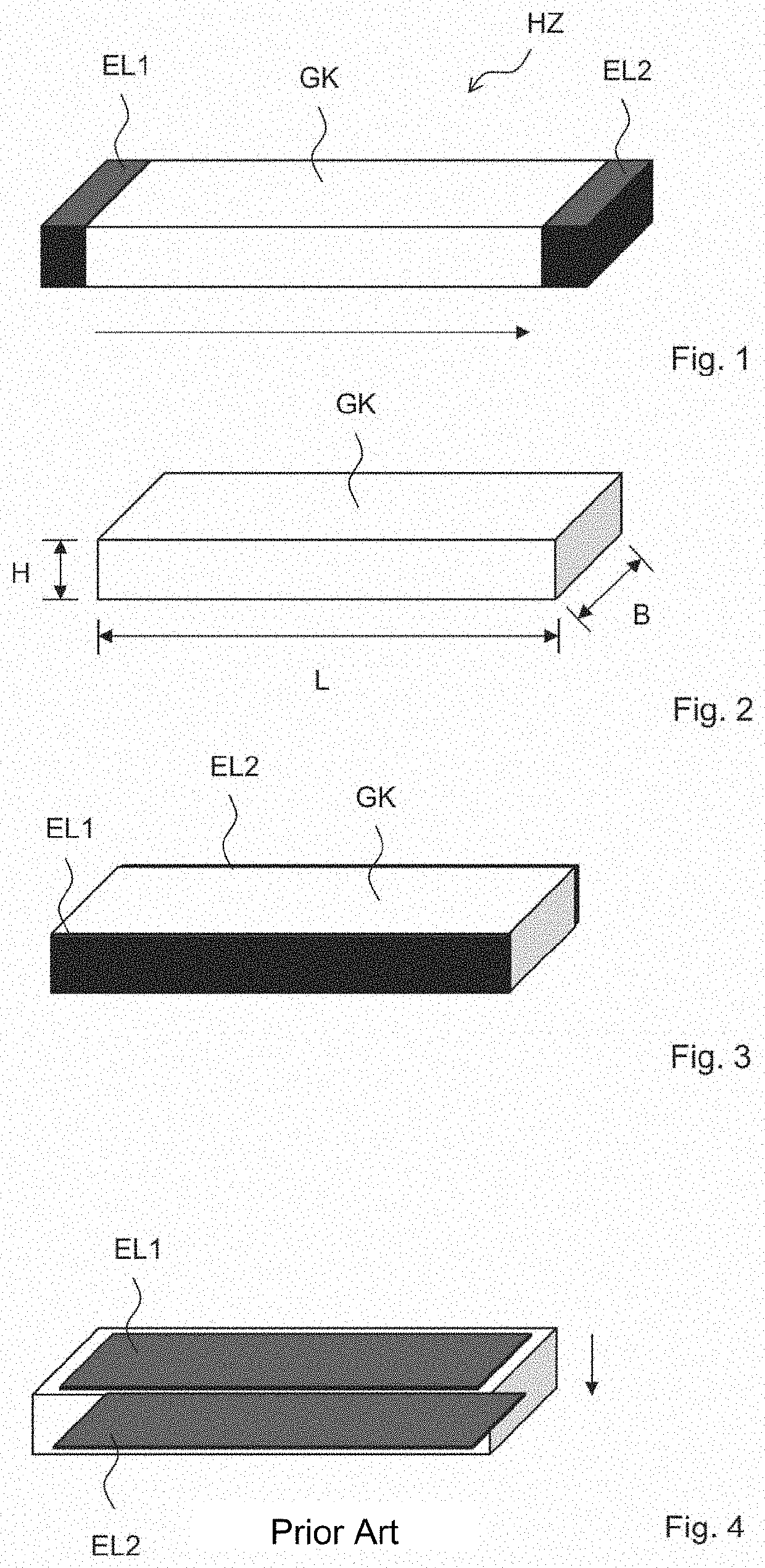
[0043]FIG. 1 shows a fundamental design, in which the heater HZ has a main body GK, which is arranged between a first electrode EL1 and a second electrode EL2. The arrow indicates a possible direction of the electrical current in this case. The main body GK has the shape of a cuboid by way of example in FIG. 1. The electrodes are arranged in this case on ends of the main body which do not have the shortest spacing. The path of the electrical current is therefore relatively long. The electrical field strength is thus reduced in the main body and the number of the grain boundaries which the electrical current has to overcome is increased.

[0044]FIG. 2 shows the meaning of the terms length, width, and height with respect to a main body. In this case, the length is essentially the greatest-possible spacing of opposing ends, sections, or surfaces of the main body GK. The height is a measure of the shortest-possible spacing of opposing surfaces, sides, ends, or sections of the main body.

[0...


PUM


Abstract

A positive temperature coefficient (PTC) heater is disclosed. In an embodiment the PTC heater includes a main body having a length L, a width B, and a height H made of a PTC material and a first electrode and a second electrode made of an electrically conductive material, wherein the following is true for L, B, and H: L≥B≥H, and wherein the electrodes are connected to the main body so that the following is true for a spacing d thereof from one another: d>H.

Description

[0001]This patent application is a national phase filing under section 371 of PCT / EP2017 / 083598, filed Dec. 19, 2017, which claims the priority of German patent application 102017101946.4, filed Feb. 1, 2017, each of which is incorporated herein by reference in its entirety.TECHNICAL FIELD[0002]The invention relates to PTC heaters, in which the switch-on current is reduced.BACKGROUND[0003]PTC heaters have a wall element made of a PTC material (PTC=Positive Temperature Coefficient), i.e., the electrical resistance of the PTC material increases with rising temperature. Such heaters can be used for converting electrical energy into thermal energy.[0004]In known PTC heaters, the PTC material is contained in a relatively thin layer. The thin layer is arranged between two electrodes. An electrical current which flows from one electrode through the PTC material to the other electrode deposits energy in the PTC material, which is converted into heat. Typically, at least one of the electrode...

Claims


Application Information

Patent Timeline
IPC IPC(8): H01C7/02H01C1/14H05B3/03H05B3/14
CPCH05B3/03H05B3/141H01C1/1406H05B2203/02H01C7/025H05K1/0212H05K2203/1115
Inventor STEINBERGER, BERNHARDBREZINA, JIRIGEPRT, MICHALSITA, ZDENEK
Owner EPCOS AG
Why Eureka
Try Eureka