Light field intraoral 3D scanner with structured light illumination

Active Publication Date: 2019-12-26
ALIGN TECH
View PDF5 Cites 35 Cited by
  • Summary
  • Abstract
  • Description
  • Claims
  • Application Information

AI Technical Summary

Benefits of technology

[0009]The use of structured light three-dimensional imaging may lead to a “correspondence problem,” where a correspondence between points in the structured light pattern and points seen by a camera viewing the pattern needs to be determined. One technique to address this issue is based on projecting a “coded” light pattern and imaging the illuminated scene from one or more points of view. Encoding the emitted light pattern makes portions of the light pattern unique and distinguishable when captured by a camera system. Since the pattern is coded, correspondences between image points and points of the projected pattern may be more easily found. The decoded points can be triangulated and 3D information recovered.
[0014]A laser diode light source and diffractive and / or refractive pattern generating optical elements may provide certain advantages in some applications. For example, the use of laser diodes and diffractive and / or refractive pattern generating optical elements may help maintain an energy efficient structured light projector so as to prevent the probe from heating up during use. Further, such components may help reduce costs by not necessitating active cooling within the probe. For example, present-day laser diodes may use less than 0.6 Watts of power while continuously transmitting at a high brightness (in contrast, for example, to a present-day light emitting diode (LED)). When pulsed in accordance with some applications of the present invention, these present-day laser diodes may use even less power, e.g., when pulsed with a duty cycle of 10%, the laser diodes may use less than 0.06 Watts (but for some applications the laser diodes may use at least 0.2 Watts while continuously transmitting at high brightness, and when pulsed may use even less power, e.g., when pulsed with a duty cycle of 10%, the laser diodes may use at least 0.02 Watts). Further, a diffractive and / or refractive pattern generating optical element may be configured to utilize most, if not all, the transmitted light (in contrast, for example, to a mask which stops some of the rays from hitting the object).
[0015]In particular, the diffraction- and / or refraction-based pattern generating optical element generates the pattern by diffraction, refraction, or interference of light, or any combination of the above, rather than by modulation of the light as done by a transparency or a transmission mask. In some applications, this may be advantageous as the light throughput efficiency (the fraction of light that goes into the pattern out of the light that falls on the pattern generator) is nearly 100%, e.g., at least 80%, e.g., at least 90%, regardless of the pattern “area-based duty cycle.” In contrast, the light throughput efficiency of a transparency mask or transmission mask pattern generating optical element is directly related to the “area-based duty cycle.” For example, for a desired “area-based duty cycle” of 100:1, the throughput efficiency of a mask-based pattern generator would be 1% whereas the efficiency of the diffraction- and / or refraction-based pattern generating optical element remains nearly 100%. Moreover, the light collection efficiency of a laser is at least 10 times higher than an LED having the same total light output, due to a laser having an inherently smaller emitting area and divergence angle, resulting in a brighter output illumination per unit area. The high efficiency of the laser and diffractive and / or refractive pattern generator may help enable a thermally efficient configuration that limits the probe from heating up significantly during use, thus reducing cost by potentially eliminating or limiting the need for active cooling within the probe. While, laser diodes and DOEs may be particularly preferable in some applications, they are by no way essential individually or in combination. Other light sources, including LEDs, and pattern generating elements, including transparency and transmission masks, may be used in other applications.
[0016]In some applications, in order to improve image capture of an intraoral scene under structured light illumination, without using contrast enhancement means such as coating the teeth with an opaque powder, the inventors have realized that a distribution of discrete unconnected spots of light (as opposed to lines, for example) may provide an improved balance between increasing pattern contrast while maintaining a useful amount of information. In some applications, the unconnected spots of light have a uniform (e.g., unchanging) pattern. Generally speaking, a denser structured light pattern may provide more sampling of the surface, higher resolution, and enable better stitching of the respective surfaces obtained from multiple image frames. However, too dense a structured light pattern may lead to a more complex correspondence problem due to there being a larger number of spots for which to solve the correspondence problem. Additionally, a denser structured light pattern may have lower pattern contrast resulting from more light in the system, which may be caused by a combination of (a) stray light that reflects off the somewhat glossy surface of the teeth and may be picked up by the cameras, and (b) percolation, i.e., some of the light entering the teeth, reflecting along multiple paths within the teeth, and then leaving the teeth in many different directions. As described further hereinbelow, methods and systems are provided for solving the correspondence problem presented by the distribution of discrete unconnected spots of light. In some applications, the discrete unconnected spots of light from each projector may be non-coded.
[0160]In some embodiments, such as any of those described above or throughout the specification, high dynamic range 3D imaging may be provided using light field imaging in combination with structured illumination. Fringe patterns may be projected onto a scene and modulated by the scene depth. Then, a structured light field may be detected using light field recording devices. The structured light field contains information about ray direction and phase-encoded depth via which the scene depth can be estimated from different directions. The multidirectional depth estimation may be able to achieve high dynamic 3D imaging effectively.

Problems solved by technology

The use of structured light three-dimensional imaging may lead to a “correspondence problem,” where a correspondence between points in the structured light pattern and points seen by a camera viewing the pattern needs to be determined.

Method used


Image

  • Light field intraoral 3D scanner with structured light illumination
  • Light field intraoral 3D scanner with structured light illumination
  • Light field intraoral 3D scanner with structured light illumination

Examples


Embodiment Construction

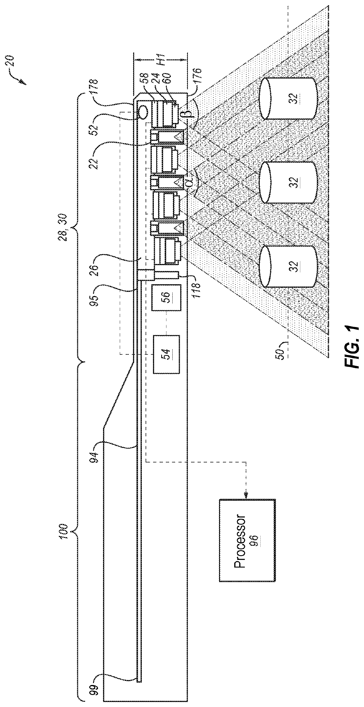
[0279]Reference is now made to FIG. 1, which is a schematic illustration of an elongate handheld wand 20 for intraoral scanning, in accordance with some applications of the present invention. A plurality of structured light projectors 22 and a plurality of cameras 24 are coupled to a rigid structure 26 disposed within a probe 28 at a distal end 30 of the handheld wand. In some applications, during an intraoral scan, probe 28 enters the oral cavity of a subject.

[0280]For some applications, structured light projectors 22 are positioned within probe 28 such that each structured light projector 22 faces an object 32 outside of handheld wand 20 that is placed in its field of illumination, as opposed to positioning the structured light projectors in a proximal end of the handheld wand and illuminating the object by reflection of light off a mirror and subsequently onto the object. Similarly, for some applications, cameras 24 are positioned within probe 28 such that each camera 24 faces an...


PUM


Abstract

A handheld wand comprises a probe at a distal end of the elongate handheld wand. The probe includes a light projector and a light field camera. The light projector includes a light source and a pattern generator configured to generate a light pattern. The light field camera includes a light field camera sensor, the light field camera sensor comprising an image sensor comprising an array of sensor pixels, and an array of micro-lenses disposed in front of the image sensor such that each micro-lens is disposed over a sub-array of the array of sensor pixels.

Description

CROSS REFERENCE TO RELATED APPLICATIONS[0001]The present application claims priority from:[0002](a) U.S. Provisional Application No. 62 / 689,006 to Saphier, filed Jun. 22, 2018, entitled, “Intraoral 3D scanner employing multiple miniature cameras and multiple miniature pattern projectors,”[0003](b) U.S. Provisional Application No. 62 / 775,787 to Atiya, filed Dec. 5, 2018, entitled, “Light field intraoral 3D scanner with structured light illumination,” and[0004](c) U.S. Provisional Application No. 62 / 778,192 to Atiya, filed Dec. 11, 2018, entitled, “Light field intraoral 3D scanner with structured light illumination.”[0005]Each of these applications is assigned to the assignee of the present application and is incorporated herein by reference in its entirety for all purposes.FIELD OF THE INVENTION[0006]The present invention relates generally to three-dimensional imaging, and more particularly to intraoral three-dimensional imaging using structured light illumination.BACKGROUND[0007]Den...

Claims


Application Information

Patent Timeline
Patent Type & Authority Applications(United States)
IPC IPC(8): A61C9/00G06T17/00G06T7/80G02B27/42H04N9/31
CPCG02B27/4227G06T17/00G02B27/4222H04N9/3161A61C9/006G06T2207/30036G06T7/80A61C9/0066A61B1/00096A61B1/00172A61B1/24A61B1/0615A61B1/00177G01B11/2513G01B11/2545G01B11/245A61B1/00009A61B1/00193G06T7/521G06T7/85G06T7/586G06T2207/10028G06T2207/10024G06T2207/10052
Inventor ATIYA, YOSSEFLAMPERT, EREZKOPELMAN, AVI
Owner ALIGN TECH
Why Eureka
Try Eureka