Ultrasonic bonding head, ultrasonic bonding device, and ultrasonic bonding method

a technology of ultrasonic bonding and ultrasonic bonding, which is applied in the direction of mechanical vibration separation, soldering apparatus, manufacturing tools, etc., can solve the problems of inapplicability of conventional ultrasonic bonding devices, large device total, and disturbance of ultrasonic vibration, so as to reduce the size of the device, prevent deformation of the vibrator unit, and increase the ultrasonic vibration

Active Publication Date: 2020-01-02
TDK CORPARATION
View PDF0 Cites 0 Cited by
  • Summary
  • Abstract
  • Description
  • Claims
  • Application Information

AI Technical Summary

Benefits of technology

[0045]In the ultrasonic bonding method according to the first and second aspects of the present invention, the holder holds the base of the vibrator unit including an ultrasonic horn in a cantilever manner. Thus, the ultrasonic bonding head according to the first and second aspects of the present invention can increase the ultrasonic vibration at the press part and can downsize the device compared to when the vibrator unit is held from both sides.
[0046]In the ultrasonic bonding method according to the present invention, the holder is provided with the restraint portion configured to contact with the vibrator unit at the counterforce dispersion position. Thus, the restraint portion can receive a part of a counterforce of the pressurizing force pressing the press part provided at the f

Problems solved by technology

In such a conventional ultrasonic bonding device, the ultrasonic horn needs to have a large length for increasing the ultrasonic vibration of the press part, and the entire device becomes large, which is a problem.
Moreover, holders of the ultrasonic horn are on both sides and may thereby disturb the ul

Method used


Image

  • Ultrasonic bonding head, ultrasonic bonding device, and ultrasonic bonding method
  • Ultrasonic bonding head, ultrasonic bonding device, and ultrasonic bonding method
  • Ultrasonic bonding head, ultrasonic bonding device, and ultrasonic bonding method

Examples


first embodiment

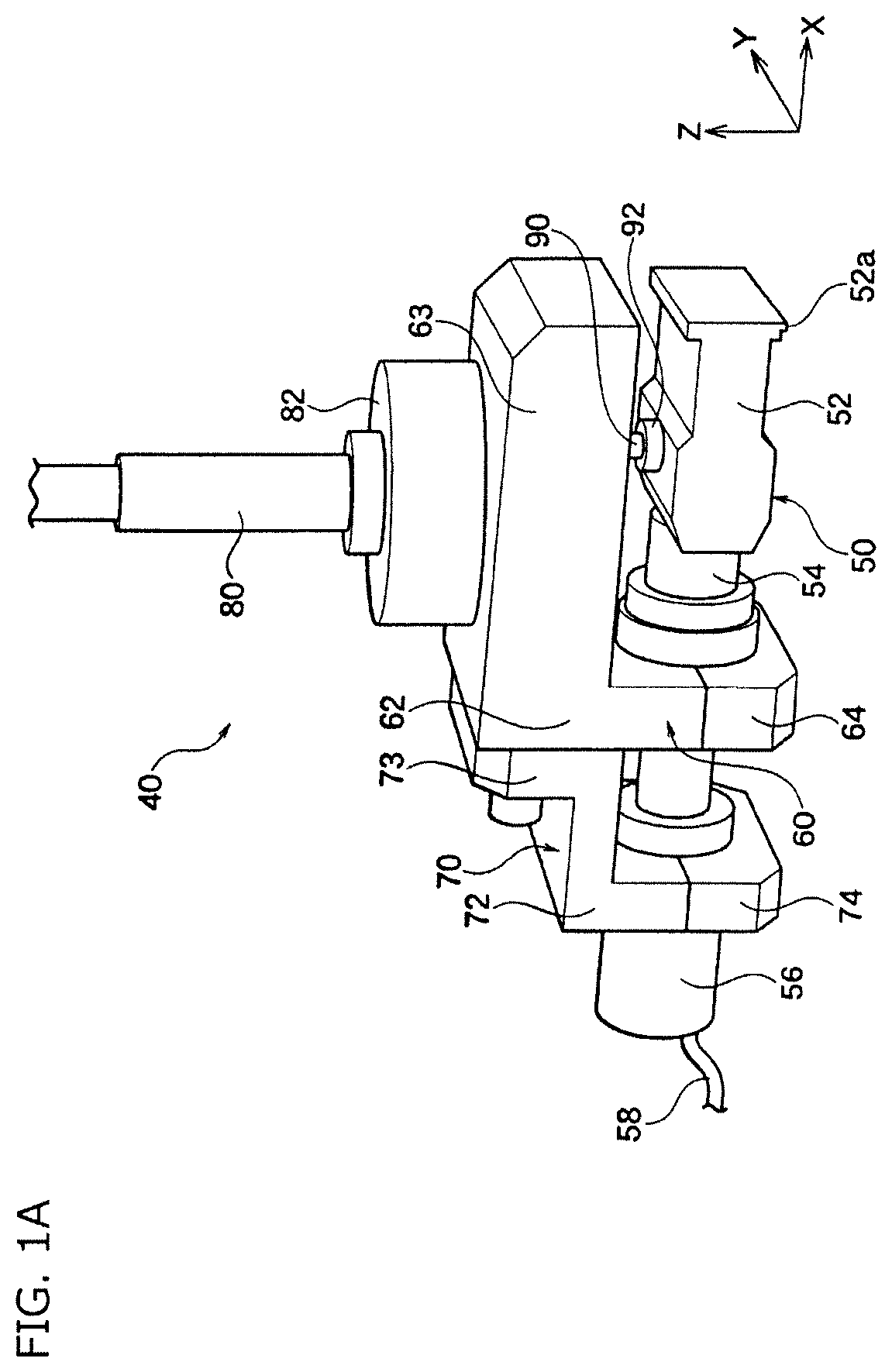
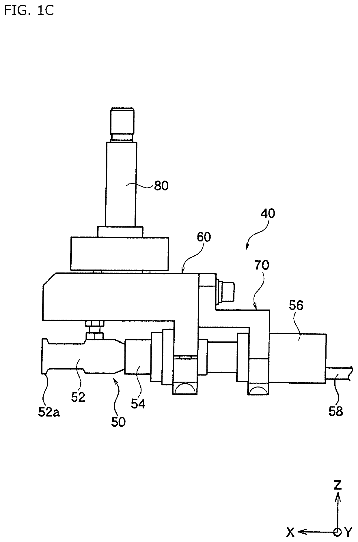
[0069]An ultrasonic bonding head 40 is described based on FIG. 1A to FIG. 1M. The ultrasonic bonding head 40 of the present embodiment includes an ultrasonic vibrator unit 50, a holder 60, and a pressurizing shaft 80. The holder 60 holds the ultrasonic vibrator unit 50. The pressurizing shaft 80 is connected with the holder 60 and moves the holder 60 and the ultrasonic vibrator unit 50 in the Z-axis direction.

[0070]As shown in FIG. 1H to FIG. 1M, the ultrasonic vibrator unit 50 includes an ultrasonic horn 52, a booster 54, and a vibration source cover 56, and these are connected in line in this order along the X-axis direction. The vibration source cover 56 contains a vibration source (not illustrated). The vibration source is not limited and is, for example, a piezoelectric element.

[0071]The vibration source is positioned and fixed inside the vibration source cover 56, but is not directly fixed to an auxiliary holder 70 mentioned below (see FIG. 1A). The vibration source vibrates b...

second embodiment

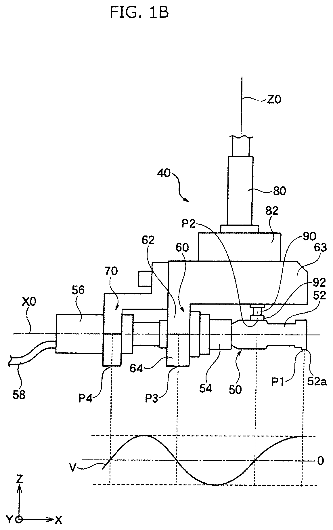
[0099]An ultrasonic bonding head according to Second Embodiment is similar to the ultrasonic bonding head 40 according to First Embodiment except that the main hold position P3 and the counterforce dispersion position P2 shown in FIG. 1B are positioned opposite in the X-axis direction as shown in FIG. 6. That is, the main hold position P3 and the counterforce dispersion position P2 are arranged in this order from the tip to the base of the ultrasonic vibrator unit 50 along the longitudinal axis X0 of the ultrasonic vibrator unit 50.

[0100]At the main hold position P3, the holder 60 holds the ultrasonic vibrator unit 50. At the counterforce dispersion position P2, the restraint pin 90 is in contact with a part of the outer circumference of the ultrasonic vibrator unit 50. The restraint pin 90 may be in contact with the ultrasonic horn 52 or the booster 54. The holder 60 may hold the ultrasonic horn 52 or the booster 54.

[0101]In the ultrasonic vibrator unit 50 according to Second Embod...

third embodiment

[0102]In Third Embodiment, described is a method of manufacturing a board bonded body 8 shown in FIG. 5B by the ultrasonic bonding method shown in FIG. 2B to FIG. 5B using the ultrasonic bonding device 2 shown in FIG. 2A including the ultrasonic bonding head 40 according to an embodiment of the present invention shown in FIG. 1A to FIG. 1G combined with the ultrasonic vibrator unit 50 shown in FIG. 1H to FIG. 1M.

[0103]As shown in FIG. 5B, the board bonded body 8 includes an electronic control board 4 (first flat member) and a flexible board 6 (second flat member). The electronic control board 4 may be a liquid crystal display panel, an organic EL display panel, or another display panel and may include, for example, a glass board.

[0104]The flexible board 6 is a board for supplying any signal and electric power to the electronic control board 4. A wiring pattern 4a of the electronic control board 4 and a wiring pattern 6a of the flexible board 6 are electrically connected to each othe...


PUM

PropertyMeasurementUnit
Forceaaaaaaaaaa
Frictionaaaaaaaaaa

Abstract

An ultrasonic bonding head includes a vibrator unit, a holder, and a pressurizing shaft. The vibrator unit includes a press part formed at a tip of the vibrator unit in a longitudinal axis thereof and configured to press a bonding scheduled part to be bonded. The holder holds a base of the vibrator unit in a cantilever manner so that the tip is a free end. The pressurizing shaft is connected with the holder and transmits a force of pressing the press part against the bonding scheduled part so that the vibrator unit moves substantially perpendicularly to the longitudinal axis. The holder is provided with a restraint portion. The restraint portion contacts with the vibrator unit at a counterforce dispersion position located between a main hold position for holding the vibrator unit by the holder and the free end.

Description

BACKGROUND OF THE INVENTION[0001]The present invention relates to an ultrasonic bonding head, an ultrasonic bonding device, and an ultrasonic bonding method.[0002]For example, the ultrasonic bonding device shown in Patent Document 1 is known. This ultrasonic bonding device carries out an ultrasonic bonding in such a manner that a press part provided at a central part of an ultrasonic horn and holding both sides of the horn in its longitudinal direction is pressed against a bonding scheduled part.[0003]In such a conventional ultrasonic bonding device, the ultrasonic horn needs to have a large length for increasing the ultrasonic vibration of the press part, and the entire device becomes large, which is a problem. Moreover, holders of the ultrasonic horn are on both sides and may thereby disturb the ultrasonic vibration.[0004]A wiring of a glass board to be a display screen board is considered to be ultrasonically bonded with a flexible printed circuit (FPC) or so, but conventional ul...

Claims


Application Information

Patent Timeline
IPC IPC(8): B23K20/10
CPCB23K20/106H01L24/74B29C65/08B29C66/80B06B3/02B23K20/10B23K20/004B23K2101/36H05K3/361H05K2203/0285H05K2203/082H05K2203/085H05K2203/1509B23K1/06
Inventor SUNAGA, SEIJIROMIYAGOSHI, TOSHINOBUOTOMO, TATSUNORI
Owner TDK CORPARATION
Why Eureka
Try Eureka