
Manufacturing method of polysilicon semiconductor layer,thin film transistor and manufacturing method

Active Publication Date: 2020-01-02
WUHAN CHINA STAR OPTOELECTRONICS SEMICON DISPLAY TECH CO LTD
View PDF0 Cites 0 Cited by
  • Summary
  • Abstract
  • Description
  • Claims
  • Application Information

AI Technical Summary

Benefits of technology

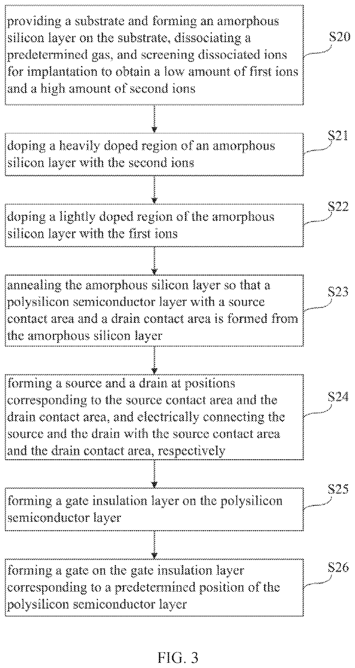
The present invention provides a method for manufacturing a polysilicon semiconductor layer, a thin film transistor, and a manufacturing method that can accurately dope ions into corresponding regions using a fast and reliable channel implantation method. This method reduces product defects, improves product quality, and decreases production costs. It uses a low amount of B2+ / B3+ ions to adjust the initial voltage of channel implantation and dopes a lightly doped region of the polysilicon layer with B2+ / B3+ ions. This solution can be used on various devices such as LTPS, OLED TFT LCDs, etc. Additionally, this method does not require the purchase of additional equipment or additional processes and can be implemented using existing machines.

Problems solved by technology

However, the channel implantation method using B+ has the following disadvantages: since amount of B+ ions dissociated from the BF3 gas is about 5 times larger than amount of B2+ ions and is much higher than amount of B3+ ions, in a production of more precise devices in a display panel, the channel implantation method using B+ ions is difficult to achieve small amount and precise control when B+ ion implantation, so that a current of the B+ ion beam cannot be smaller and more stable, and the channel implantation cannot be controlled very accurately.

Method used


Image

  • Manufacturing method of polysilicon semiconductor layer,thin film transistor and manufacturing method
  • Manufacturing method of polysilicon semiconductor layer,thin film transistor and manufacturing method
  • Manufacturing method of polysilicon semiconductor layer,thin film transistor and manufacturing method

Examples


Embodiment Construction

[0039]The following embodiments refer to the accompanying drawings for exemplifying specific implementable embodiments of the present disclosure. Moreover, directional terms described by the present disclosure, such as upper, lower, front, back, left, right, inner, outer, side, etc., are only directions by referring to the accompanying drawings, and thus the used directional terms are used to describe and understand the present disclosure, but the present disclosure is not limited thereto. In the drawings, the same reference symbol represents the same or similar components.

[0040]In the prior art method for manufacturing a polysilicon semiconductor layer, since it is difficult to achieve small amount and precise control when B+ ion implantation, so a channel implantation cannot be controlled very accurately. This embodiment of the present disclosure can solve the technical problem.

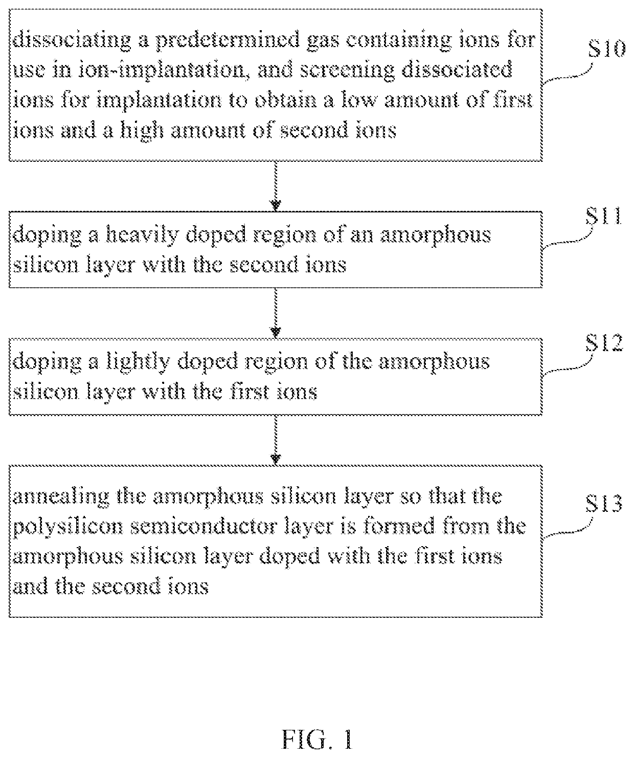
[0041]Referring to FIG. 1, which is a flow chart of a method for manufacturing a polysilicon semiconduct...


PUM


Abstract

A method for manufacturing a polysilicon semiconductor layer, a thin film transistor, and a manufacturing method are provided. The method for manufacturing a polysilicon semiconductor layer includes the following steps. A predetermined gas is dissociated, and a low amount of first ions and a high amount of second ions are screened out. A heavily doped region is doped with the second ions. A lightly doped region is doped with the first ions. Annealing is further performed, so that a polysilicon semiconductor layer is formed from an amorphous silicon layer.

Description

FIELD OF DISCLOSURE[0001]The present disclosure relates to the field of display manufacturing technologies, and more particularly to a method for manufacturing a polysilicon semiconductor layer, a thin film transistor, and a manufacturing method.BACKGROUND[0002]In response to a rise of hand-held smart mobile devices, performance and high-quality requirements for display panels have become higher and higher. In order to increase product reliability, current mainstream product process design, requiring channel implantation (Vth), is one of the main focuses. As an aperture ratio of a current display panel is getting larger and larger, and production of some internal devices is becoming more and more precise, how to adjust a manufacturing method more stably and minutely becomes more important.[0003]Currently, a channel implantation (Vth) method uses B+ ions to improve a Vth start voltage, for example, doping of a polysilicon layer in a thin film transistor. Since a lightly doped portion...

Claims


Application Information

Patent Timeline
IPC IPC(8): H01L29/66H01L21/02H01L21/265
CPCH01L21/02667H01L29/66757H01L29/66765H01L21/02592H01L29/66537H01L21/02532H01L21/26513H01L21/26506H01L21/324H01L29/78621H01L29/78675
Inventor LU, MING-JEN
Owner WUHAN CHINA STAR OPTOELECTRONICS SEMICON DISPLAY TECH CO LTD
Learn More