Antenna module and communication device

a technology of antenna module and communication device, which is applied in the direction of resonant antenna, substantially flat resonant element, and semiconductor/solid-state device details, etc., can solve the problems of rf characteristics that may become deteriorated, and achieve the effects of improving rf characteristics, deteriorating rf characteristics, and improving rf characteristics

Active Publication Date: 2020-01-09
MURATA MFG CO LTD
View PDF0 Cites 11 Cited by
  • Summary
  • Abstract
  • Description
  • Claims
  • Application Information

AI Technical Summary

Benefits of technology

[0028]If the radio frequency signals by the patch antennas propagate to the signal terminal, an unexpected trouble occurs such that the degree of phase shift cannot be adjusted as desired by the phase adjustment circuit, thereby making the RF characteristics deteriorated. By contrast, according to the present aspect, an influence to be given by the above-described radio frequency signals on the signal terminal can be reduced. Therefore, deterioration in RF characteristics caused by inputting, to the phase adjustment circuit, the radio frequency signals propagating from the plurality of patch antennas to the signal terminal can be reduced, and an improvement in RF characteristics can be intended.

Problems solved by technology

However, in the above-described conventional structure, the RF characteristics may become deteriorated due to the influence of a radio frequency signal emitted from any of the patch antennas into space or a radio frequency signal in space received by any of the patch antennas.
This problem is particularly significant in, for example, millimeter waves, in which the radio frequency signals tend to propagate to the signal terminals.

Method used


Image

  • Antenna module and communication device
  • Antenna module and communication device
  • Antenna module and communication device

Examples


embodiment

[1. Antenna Module]

[1-1. Structure]

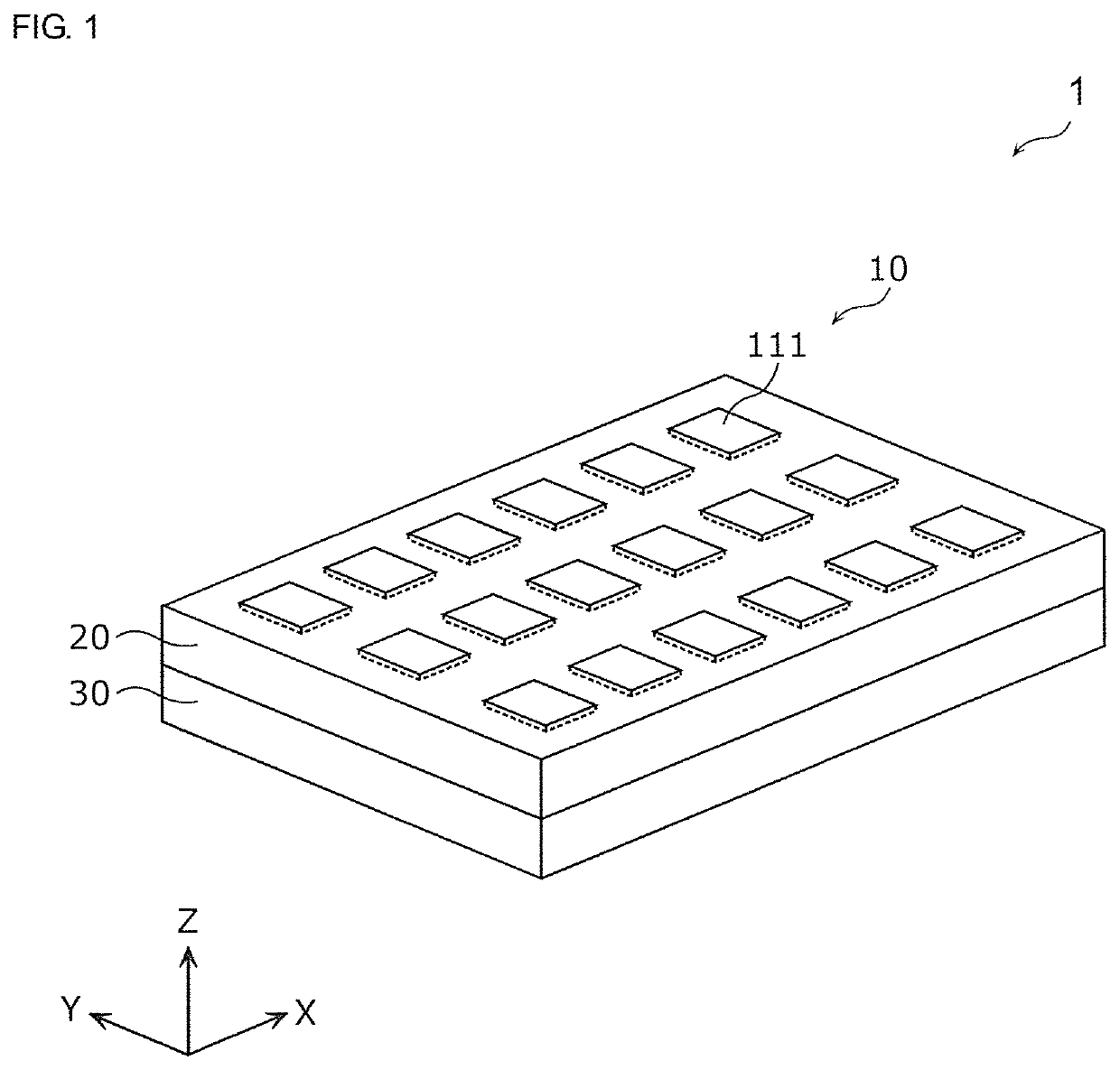
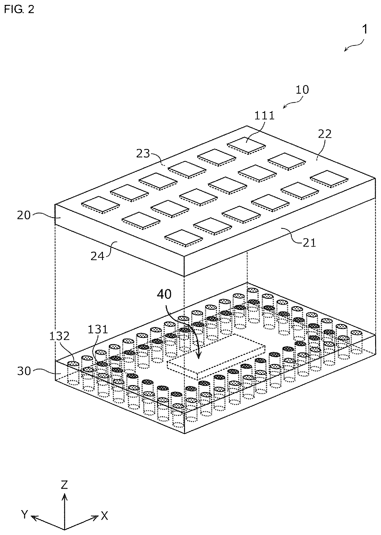
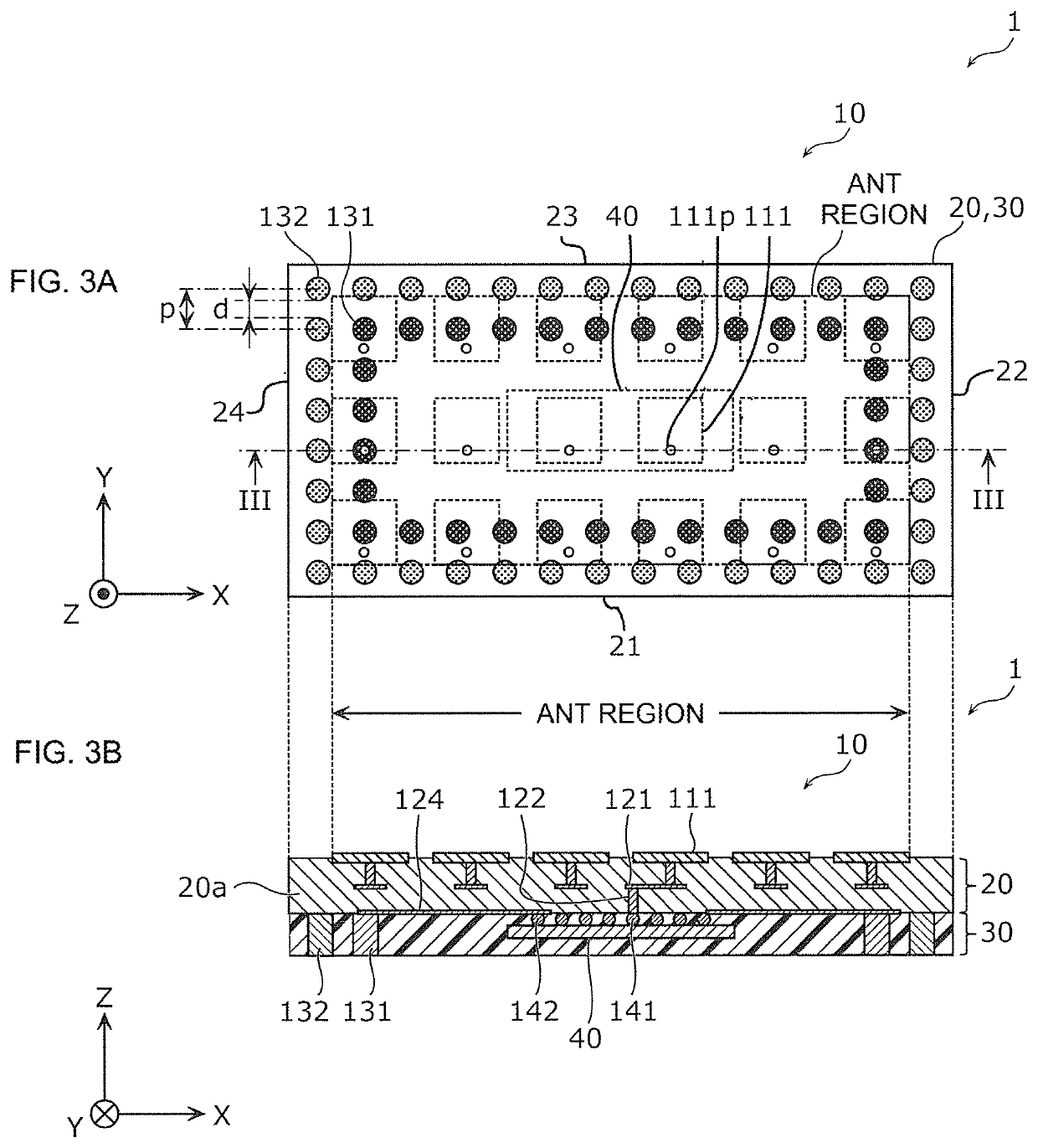
[0049]FIG. 1 to FIGS. 3A and 3B are diagrams depicting the structure of an antenna module 1 according to an embodiment. Specifically, FIG. 1 is an external perspective view of the antenna module 1 according to the embodiment. FIG. 2 is an exploded perspective view of the antenna module 1 according to the embodiment. More specifically, in the drawing, a state is depicted in which a dielectric substrate 20 and a sealing member 30 are separated. FIGS. 3A and 3B depict a plan view and a sectional view of the antenna module 1 according to the embodiment, respectively. More specifically, FIG. 3A depicts a plan view when the antenna module 1 is viewed from an upper surface side (Z-axis plus side in the drawing) by seeing through the dielectric substrate 20, and FIG. 3B depicts a sectional view on a III-III line in FIG. 3A.

[0050]In the following, description is made by taking a thickness direction of the antenna module 1 as a Z-axis direction and direction...

modification example 1

[0137]FIG. 8 is a plan view of an antenna module 1A according to a modification example 1 of the present embodiment. Note that the drawing depicts a plan view when the antenna module 1A is viewed from an upper surface side (Z-axis plus side in the drawing) by seeing through the dielectric substrate 20. The same goes for a plan view of each of the following modification examples.

[0138]As depicted in the drawing, compared with the antenna module 1 according to the embodiment, the antenna module 1A according to the present modification example is different in that, furthermore, when viewed from a direction perpendicular to the first main surface of the dielectric substrate 20 (that is, when viewed from the Z-axis plus side), the ground terminal (here, ground conductor post 132) is arranged between each signal terminal (here, signal conductor post 131) and the radio frequency circuit component (here, RFIC 40). That is, at least one of the plurality of ground terminals included in the an...

modification example 2

[0142]FIG. 9 is a plan view of an antenna module 1B according to a modification example 2 of the embodiment.

[0143]As depicted in the drawing, compared with the antenna module 1 according to the embodiment, the antenna module 1B according to the present modification example is different in that, when viewed from a direction perpendicular to the first main surface of the dielectric substrate 20 (that is, when viewed from the Z-axis plus side), the plurality of ground terminals (here, ground conductor posts 132) arranged as being aligned along the side surface 22 of the dielectric substrate 20 and the plurality of ground terminals arranged as being aligned along the side surface 24 of the dielectric substrate 20 are not provided. That is, when viewed from that perpendicular direction, for each signal terminal (here, signal conductor post 131), the antenna module 1B only has a ground terminal arranged between the signal terminal and the closest first side surface (side surface 21 or sid...


PUM

PropertyMeasurementUnit
relative permittivityaaaaaaaaaa
radio frequencyaaaaaaaaaa
wave lengthaaaaaaaaaa

Abstract

An antenna module (1) according to the present disclosure has a dielectric substrate (20), an array antenna (10) including a plurality of patch antennas (111), an RFIC (40) electrically connected to the plurality of patch antennas (111), a signal conductor post (131) electrically connected to the RFIC (40), and a ground conductor post (132) set at a ground potential. The ground conductor post (132) is arranged, when viewed from a direction perpendicular to a first main surface of the dielectric substrate (20), between the signal conductor post (131) and a first side surface closest to the signal conductor post (131) of the dielectric substrate (20) in a polarizing direction of radio frequency signals to be emitted or received by the plurality of patch antennas (111).

Description

[0001]This is a continuation of International Application No. PCT / JP2018 / 008748 filed on Mar. 7, 2018 which claims priority from Japanese Patent Application No. 2017-054214 filed on Mar. 21, 2017. The contents of these applications are incorporated herein by reference in their entireties.BACKGROUND OF THE DISCLOSUREField of the Disclosure[0002]The present disclosure relates to an antenna module and a communication device.Description of the Related Art[0003]As an antenna module having patch antennas for wireless communication and a radio frequency circuit component integrated together, a structure is suggested in which patch antennas are arranged on a first main surface side of a dielectric substrate and a radio frequency element (that is, a radio frequency circuit component) is mounted on a second main surface opposite to the first main surface of the dielectric substrate (for example, refer to Patent Document 1). And, with a ground layer (that is a ground pattern conductor) provide...

Claims


Application Information

Patent Timeline
Patent Type & Authority Applications(United States)
IPC IPC(8): H01Q9/04H01Q9/06
CPCH01Q9/0485H01Q9/06H01Q9/045H01Q21/065H01Q1/2283H01Q9/0414H01Q9/0457H01Q9/0407H01L2223/6677H01L23/66
Inventor ASAKA, ATSUSHI
Owner MURATA MFG CO LTD
Why Eureka
Try Eureka