
Hemodialysis system with ultrafiltration controller

a technology of hemodialysis and controller, which is applied in the field of artificial kidney systems, can solve the problems of hemodialysis suffering from numerous drawbacks, requiring more frequent treatment at home, and requiring renal failure, so as to reduce the areas of potential danger to a patient and enhance patient safety

Active Publication Date: 2020-01-16
DIALITY INC
View PDF1 Cites 1 Cited by
  • Summary
  • Abstract
  • Description
  • Claims
  • Application Information

AI Technical Summary

Benefits of technology

The patent describes a hemodialysis system that is portable, lightweight, and easy to use. It is patient-friendly and can be used at home. The system uses disposable cartridges and does not require flexible tubing, which reduces the risk of danger to patients. The system also uses pumps that do not squeeze blood, and provides enhanced patient safety with the ability to control ultrafiltration and reverse ultrafiltration.

Problems solved by technology

Failure to properly remove these waste products can result in renal failure.
Unfortunately, hemodialysis suffers from numerous drawbacks.
However, home hemodialysis requires more frequent treatment.
Current home hemodialysis systems are big, complicated, intimidating and difficult to operate.
The equipment requires significant training.
Home hemodialysis systems are expensive and require a high initial monetary investment, particularly compared to in-center hemodialysis where patients are not required to pay for the machinery.
Present home hemodialysis systems do not adequately provide for the reuse of supplies, making home hemodialysis economically less feasible to medical suppliers.
Because of the above mentioned disadvantages, very few motivated patients undertake the drudgery of home hemodialysis.
These roller pumps are expensive and inefficient.
Also troubling, roller pumps for use in hemodialysis can cause damage to blood platelets and introduces the risk of coagulation.

Method used


Image

  • Hemodialysis system with ultrafiltration controller
  • Hemodialysis system with ultrafiltration controller
  • Hemodialysis system with ultrafiltration controller

Examples


Embodiment Construction

[0070]While the present invention is susceptible of embodiment in various forms, as shown in the drawings, hereinafter will be described the presently preferred embodiments of the invention with the understanding that the present disclosure is to be considered as an exemplification of the invention, and it is not intended to limit the invention to the specific embodiments illustrated.

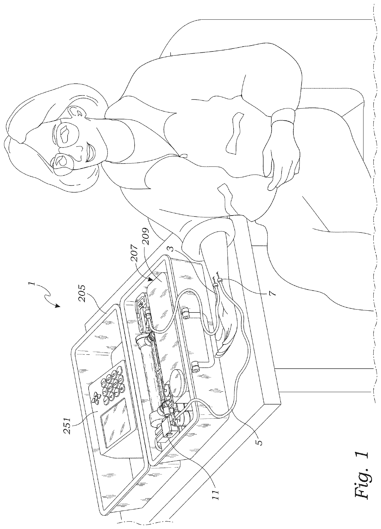
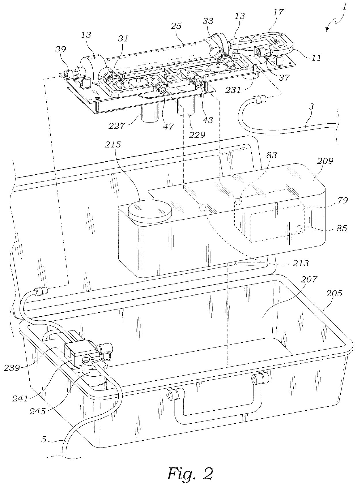
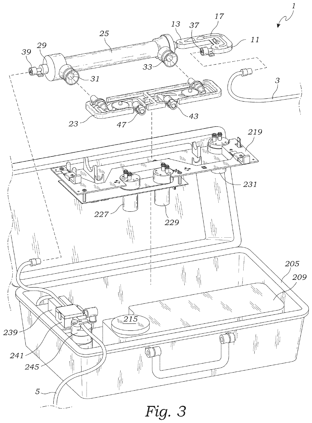
[0071]With reference to FIGS. 1-25, the hemodialysis system 1 of the present invention includes a reused dialysis machine 201, a disposable cartridge 11, an arterial blood line 3 including a needle 7 for connecting to a patient's artery, and a venous blood line 5 including a needle 7 for connecting to a patient's vein. With reference particularly to FIGS. 1-5 and 15, the disposable cartridge 11 includes a housing 13 having conduits 17 providing a blood flow path 15 and conduits 21 providing a dialysate flow path 19. Preferably the cartridge's blood flow path and dialysate flow path are conduits with an ...


PUM


Abstract

The hemodialysis system includes a closed loop dialysate flow path which includes a dialyzer and a reservoir for storing dialysate, and a closed loop blood flow path which passes through the dialyzer in the opposite direction as the dialysate flow path. In addition, the hemodialysis system includes pumps for pumping dialysate and blood through their respective flow paths, a flow sensor for measuring the flow rate of dialysate in the dialysate flow path, and a level sensor for measuring the level of dialysate in the dialysate reservoir. A processor is connected to the flow sensor, reservoir level sensor and pumps to provide a first closed loop control system including the processor, flow sensor and a first dialysate pump, and a second closed loop control system including the processor, level sensor and a second dialysate pump which enable the processor to initiate, monitor and maintain ultrafiltration.

Description

RELATED APPLICATIONS[0001]The present application is a continuation-in-part of U.S. patent application Ser. No. 16 / 223,686 filed Dec. 18, 2018, which in turn, is a continuation of U.S. patent application Ser. No. 15 / 794,995 filed Oct. 26, 2017, now U.S. Pat. No. 10,155,078 issued Dec. 18, 2018, which in turn is a continuation of U.S. patent application Ser. No. 15 / 590,823 filed May 9, 2017, now U.S. Pat. No. 9,801,992 issued Oct. 31, 2017, which in turn is a divisional of U.S. patent application Ser. No. 14 / 754,059 filed Jun. 29, 2015 now U.S. Pat. No. 9,649,420 issued May 16, 2017, which in claims benefit of expired U.S. Provisional Patent Application Ser. No. 62 / 049,742 filed on Sep. 12, 2014. The contents of the aforementioned application are incorporated by reference herein.BACKGROUND OF THE INVENTION[0002]The present invention relates to an artificial kidney system for use in providing dialysis. More particularly, the present invention is directed to a hemodialysis system incor...

Claims


Application Information

Patent Timeline
IPC IPC(8): A61M1/16A61M1/26A61M1/36
CPCA61M1/267A61M1/3626A61M1/1645A61M2205/27A61M1/1672A61M1/3661A61M1/1621A61M1/1658A61M2205/33A61M1/16A61M1/1654A61M2205/3327A61M2205/127A61M2205/126A61M2205/3303A61M2205/125A61M2205/3334A61M2205/3306A61M2205/3379A61M1/1605A61M2205/50A61M1/1609A61M2205/3653A61M2205/3368A61M1/1601A61M2205/15A61M1/1696A61M2205/3337A61M1/1603A61M2205/75A61M2205/3389A61M1/1607A61M2205/3317A61M1/1692A61M2205/3313A61M1/155A61M1/362227A61M1/154A61M1/156A61M1/36226A61M1/1524A61M1/362264A61M1/15632A61M1/36224A61M1/36225
Inventor GIORDANO, RENATOCORDER, RODNEY
Owner DIALITY INC
Learn More