Driver system

a technology of drive shafts and driveshafts, applied in the direction of pulse technique, electroluminescent light sources, electric lighting sources, etc., can solve the problems of complex and costly overall circuit design

Active Publication Date: 2020-01-16
LEE IN OK
View PDF0 Cites 0 Cited by
  • Summary
  • Abstract
  • Description
  • Claims
  • Application Information

AI Technical Summary

Benefits of technology

[0007]According to the invention, a primary object is to provide a driver system, where a simple circuit architecture is used to output a control vo

Problems solved by technology

1. For typical remote control techniques including infrared transmission and Bluetooth technology, the transmitter and the receiver need to be paired with each other, that is, the receiver will only respond to the remote control signal from the transmitter that is paired with. Therefore, the user still has to use a specific or paired remote control to control the operation state of the lighting device wirelessly.
2.

Method used


Image

  • Driver system
  • Driver system
  • Driver system

Examples


first embodiment

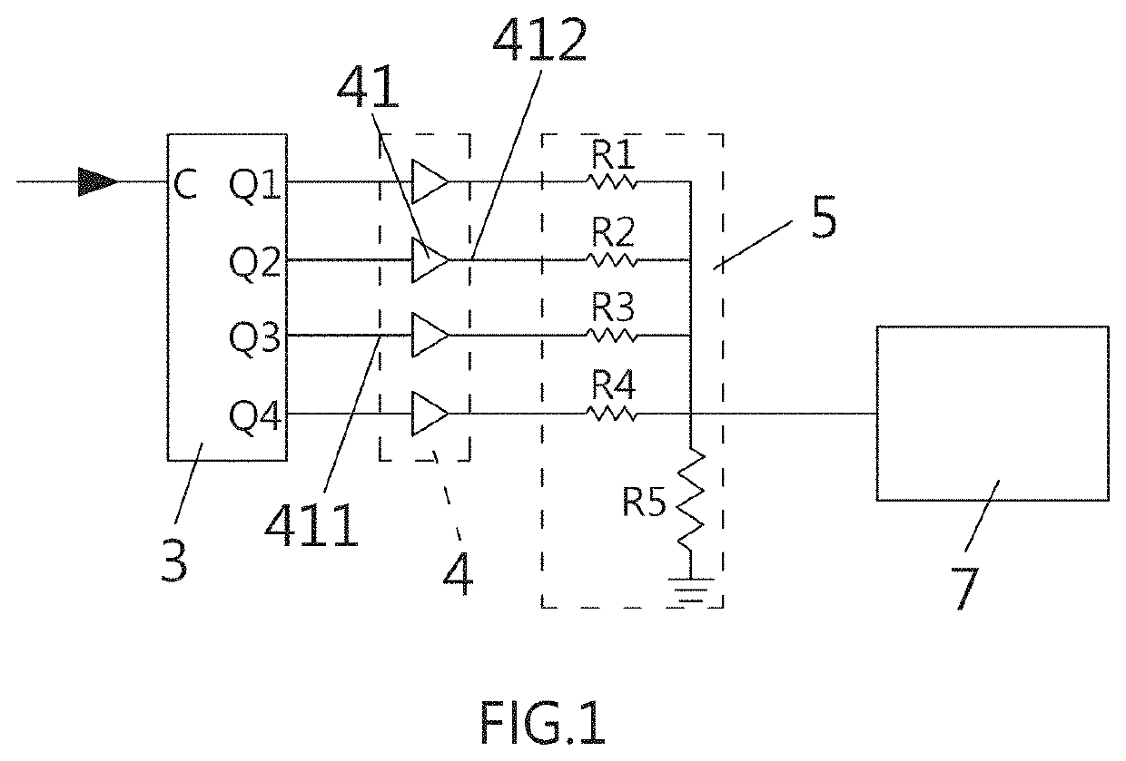
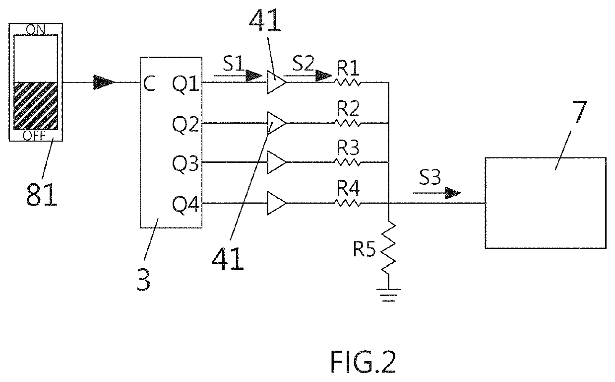
[0027]FIG. 1 is a schematic diagram showing the circuit of the driver system according to the invention. The driver system disclosed herein comprises a counter unit 3, a buffer unit 4, and a voltage regulation unit 5.

[0028]The counter unit 3 includes a first input terminal C adapted to receive a driving signal and a plurality of first output terminals Q1, Q2, Q3, and Q4. Responsive to receiving the driving signal, the counter unit 3 sequentially activates the first output terminals Q1, Q2, Q3, and Q4, one at a time, following a predetermined counting sequence, thereby outputting a control signal. The counter unit 3 may comprise a Johnson counter and is adapted to sequentially output control signals from the output terminals Q1, Q2, Q3, and Q4 according to the received driving signal. It is known in the art that the number of first output terminals is not limited to that described herein, and additional counter unit(s) may be included in the device. A plurality of counter units can b...

second embodiment

[0039]FIG. 4 is a schematic diagram showing the circuit of the driver unit according to the invention. The driver unit comprises a rectifier circuit 61, a voltage stabilization circuit 63 and a constant current circuit 64. The voltage stabilization circuit 63 includes a resistor R6, a Zener diode Z connected in series with the resistor R6, and a first operational amplifier 633. The serially connected resistor R6 and Zener diode Z are electrically connected to the rectifier circuit 61 to receive the DC power source, thereby generating a constant voltage based on the DC power source. The first operational amplifier 633 is adapted to output a predetermined voltage upon receiving the constant voltage and the control voltage. The constant current circuit 64 includes a transistor Q and a resistor R7 connected in series. The constant current circuit 64 is connected in series with the light-emitting diodes mounted in the light source module 71. The transistor Q is adapted to drive the light...

third embodiment

[0042]FIG. 6 is a schematic diagram showing the driver system according to the invention. The driver system comprises a counter unit 3, a voltage regulation unit 5 and an operational amplifier unit 9, which differs from the embodiments above in the provision of the operational amplifier unit 9, in place of the buffer unit according to the embodiments above, for connection to the voltage regulation unit 5. The voltage regulation unit 5 is similarly provided with resistors R1-R4 connected to the first output terminals Q1, Q2, Q3, Q4, respectively. The control signal output from the activated first output terminal Q1, Q2, Q3, Q4 of the counter unit is transmitted through one of the resistors in the voltage regulation unit 5 to reach the operational amplifier unit 9, which conducts computation based on the control signal and then outputs a specific control voltage. The control voltage output is isolated due to the provision of the operational amplifier unit 9. The operational amplifier ...


PUM


Abstract

The present invention relates to a driver system, comprising a counter unit, a buffer unit and a voltage regulation unit. The counter unit is adapted to sequentially activate one of the first output terminals upon receiving a driver signal and then output a control signal according to the driver signal. The buffer unit is adapted to output an isolated control signal upon receiving the control signal from the counter unit. Upon receiving the isolated control signal, the voltage regulation unit outputs a control voltage which corresponds to a given resistor provided therein. The control voltage is useful in driving an electronic device, and the operation of the electronic device may be further adjusted by changing the control voltage from one level to another.

Description

PRIORITY CLAIM CROSS REFERENCE TO RELATED APPLICATIONS[0001]This application is a 371 of International Application No. PCT / CN2017 / 086272 filed May 27, 2017, the entirety of which is hereby incorporated by reference in their entirety.BACKGROUND OF THE INVENTION1. Field of the Invention[0002]The present invention relates to a driver system, in which a simple circuit architecture is used to output a control voltage following the counting sequence of a counter unit, thereby shifting the operation of an electrical device from one operation state to another.2. Description of Related Art[0003]Light-emitting diodes (abbreviated hereafter as LEDs) are a type of luminous semiconductor electronic devices developed as early as in 1962. They can only emit red light with low brightness in the early days and were later on developed to function as the light sources for emitting monochromatic light other than red light. Nowadays, LEDs are available in many wavelengths for emitting visible light, inf...

Claims


Application Information

Patent Timeline
IPC IPC(8): H05B37/02H05B33/08H05B44/00
CPCH05B45/10H05B47/10H03J9/06H05B47/17H05B47/195H03K23/542H05B45/30
Inventor LEEHUANG, KUO-CHUNG
Owner LEE IN OK
Why Eureka
Try Eureka