Multi-layer construction element, method for production thereof and process line for production of the multi-layer construction element

a technology of multi-layer construction and production method, applied in the field of construction, can solve the problems of complex manufacture, difficult production of multi-layer panels on the proposed line, and possible shrinkage, and achieve the effect of low energy consumption and simple production method

Inactive Publication Date: 2020-01-23
MAKHALIN ALEXEI IGOREVICH
View PDF0 Cites 0 Cited by
  • Summary
  • Abstract
  • Description
  • Claims
  • Application Information

AI Technical Summary

Benefits of technology

[0009]The purpose of the proposed invention is to create a simple and convenient multi-layer construction element to combine in structures that results in a minimum shrinkage with the possibility of using a multi-layer construction element for building bearing walls, internal partitions, floors and ceilings, as well as the production of ready-made walls with all the working holes by gluing and fastening in the production; a high-performance process line for multi-layer construction elements using well-known equipment with low energy consumption, as well as the possibility of supplying outer vertically oriented elements, and continuous and low-cost method of manufacturing multi-layer construction elements.

Problems solved by technology

The disadvantage of this development is that the beam element has additional inner spacing elements, shrinkage is possible due to the presence of slopes on the outer side of each outer layer, and the manufacture is complex due to the fact that it is produced with joints and protrusions.
The disadvantage of this development is that the production of multi-layer panels on the proposed line is difficult, and therefore productivity is not high.
The disadvantage of this development is a large number of labour-intensive operations and as a consequence, the complexity of production and high time costs.

Method used


Image

  • Multi-layer construction element, method for production thereof and process line for production of the multi-layer construction element
  • Multi-layer construction element, method for production thereof and process line for production of the multi-layer construction element
  • Multi-layer construction element, method for production thereof and process line for production of the multi-layer construction element

Examples


Embodiment Construction

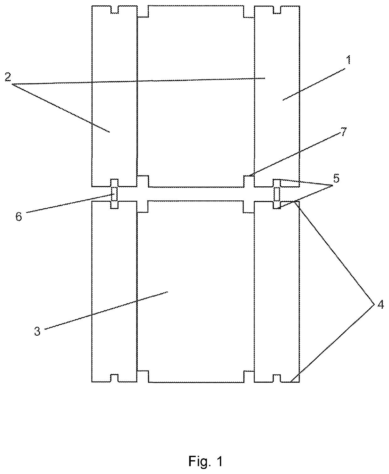
[0018]Multi-layer construction element (1) includes outer elements (2) and thermal insulation layer (3) placed between them made, for example, of polyurethane foam, polystyrene, polystyrene foam, urea formaldehyde foam, polycarbonate (polyurea). Due to the unique properties of these materials, thermal insulation layer (3) easily takes on the desired shape and is an excellent thermal and sound insulation. The materials used for the thermal insulation layer are also resistant to different weather conditions. The upper and lower surface (4) of the outer elements (2) of the multi-layer construction element (1) is made with a longitudinal joint (5) along the entire outer element (2). The multi-layer construction element (1) additionally contains longitudinal connecting elements (6) that are included in the joints (5) of the upper and lower surface (4) of outer elements (2). The connecting element (6) allows for easy formation of a construction structure of multi-layer construction elemen...


PUM

PropertyMeasurementUnit
temperatureaaaaaaaaaa
heightaaaaaaaaaa
thicknessaaaaaaaaaa

Abstract

The invention relates to construction and is intended to create a multilayer structural element that is simple and convenient for combining in a structure and provides minimum shrinkage with the possibility for use in building load-bearing walls, interior partitions, floors and ceilings, as well as for manufacturing prefabricated walls having all process openings by means of bonding and ties during manufacturing; a high-capacity production line for producing a multilayer structural element using equipment consuming low levels of energy; and to enable the supply of vertically oriented exterior elements, as well as a continuous and low-cost method for manufacturing a multilayer structural element. The multilayer structural element includes exterior elements and a heat-insulating layer therebetween. The top and bottom surface of the exterior elements have a longitudinal groove along the entire exterior element. The multilayer structural element enables both horizontal and vertical installation.

Description

CROSS-REFERENCE TO RELATED APPLICATIONS[0001]The present patent application is National stage application of the PCT application PCT / RU2018 / 000183 filed on Mar. 23, 2018 which claims priority to Russian patent application RU2017112072 filed Apr. 10, 2017.FIELD OF THE INVENTION[0002]The invention refers to construction, namely to multi-layer construction elements containing a thermal insulation layer.BACKGROUND OF THE INVENTION[0003]The patent of the Russian Federation for utility model No. 41321 “Beam Element” is known. IPC E04C3 / 12, E04B1 / 10. The utility model belongs to the long bearing construction elements, namely the beam elements, and can be used for the construction of various buildings. Character of the utility model. The beam element includes outer layers of wood, spacers placed between them, and inner thermal insulation layer of polyurethane foam; the ratio of the total thickness of outer layers to the thickness of the thermal insulation layer is 0.2-10. The inner surfaces...

Claims


Application Information

Patent Timeline
Patent Type & Authority Applications(United States)
IPC IPC(8): B28B11/00E04B1/14
CPCE04C2/288B28B11/00B32B2315/06B32B2607/00E04B1/14E04C1/40E04C2002/004E04C1/41E04B2/08E04B2002/0247E04B2002/0282
Inventor MAKHALIN, ALEXEI IGOREVICH
Owner MAKHALIN ALEXEI IGOREVICH
Why Eureka
Try Eureka