High-G Shock Testing Machine

a shock testing machine and high-g technology, applied in the direction of brake systems, instruments, transportation and packaging, etc., can solve the problems of high labor intensity, high labor intensity, and high cost of both testing methods

Active Publication Date: 2020-01-23
OMNITEK PARTNERS LLC
View PDF0 Cites 1 Cited by
  • Summary
  • Abstract
  • Description
  • Claims
  • Application Information

AI Technical Summary

Benefits of technology

[0008]It is therefore an object to develop a low-cost, reusable testing method and accompanying experimental and simulation capabilities that can reproduce acceleration/time profiles representative of weapon target penetration as well as shock loading experienced

Problems solved by technology

Similar but more complex combinations of axial as well as lateral and bending shock loadings are experienced by air dropped weapons as they impact the target, particularly when the weapon is rocket assisted to achieve high impact velocities and when the target structure is highly heterogeneous, such as reinforced concrete or soil with large rock content.
However, the corresponding change in velocity typically requires ballistic or operational testing.
Both testing methods are extremely costly, personnel intensive, and introduce both technical and safety risks.
Currently, there is no one shock testing apparatus that can shock test aircraft components to accommodate the varying shoc

Method used


Image

  • High-G Shock Testing Machine
  • High-G Shock Testing Machine
  • High-G Shock Testing Machine

Examples


second embodiment

[0052]shock and shock / tail-slap testing machines are for applying short duration and high acceleration / deceleration pulses, such as of over ±10,000 g over durations of e.g., over 5 msec. These shock loading machine concepts can apply one or a combination of shock loading pulses to the article being tested, such as an ordinance, in axial and lateral directions to simulate almost any shock loading events, including tail slap, where large lateral accelerations / decelerations are introduced due to the bending and rebound in the lateral direction. For purposes of this disclosure, “tail-slap” means a shock loading event in a direction perpendicular to its intended motion, such intended motion being in a direction of penetration with regard to an ordinance. For other articles being testing, the term shock loading event is merely in a direction created by the machine with regard to an orientation of the article being tested in the machine.

[0053]The first embodiment of shock and shock / tail-sl...

first embodiment

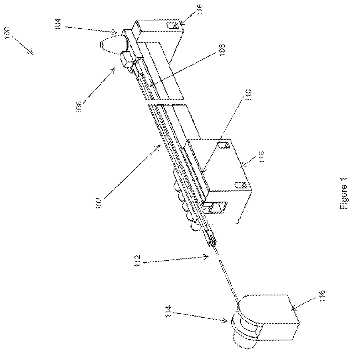
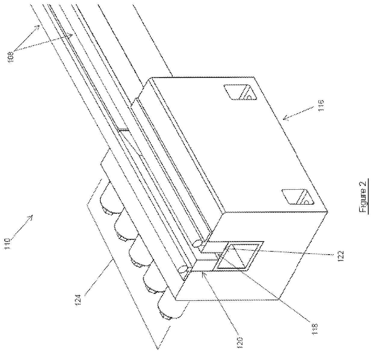
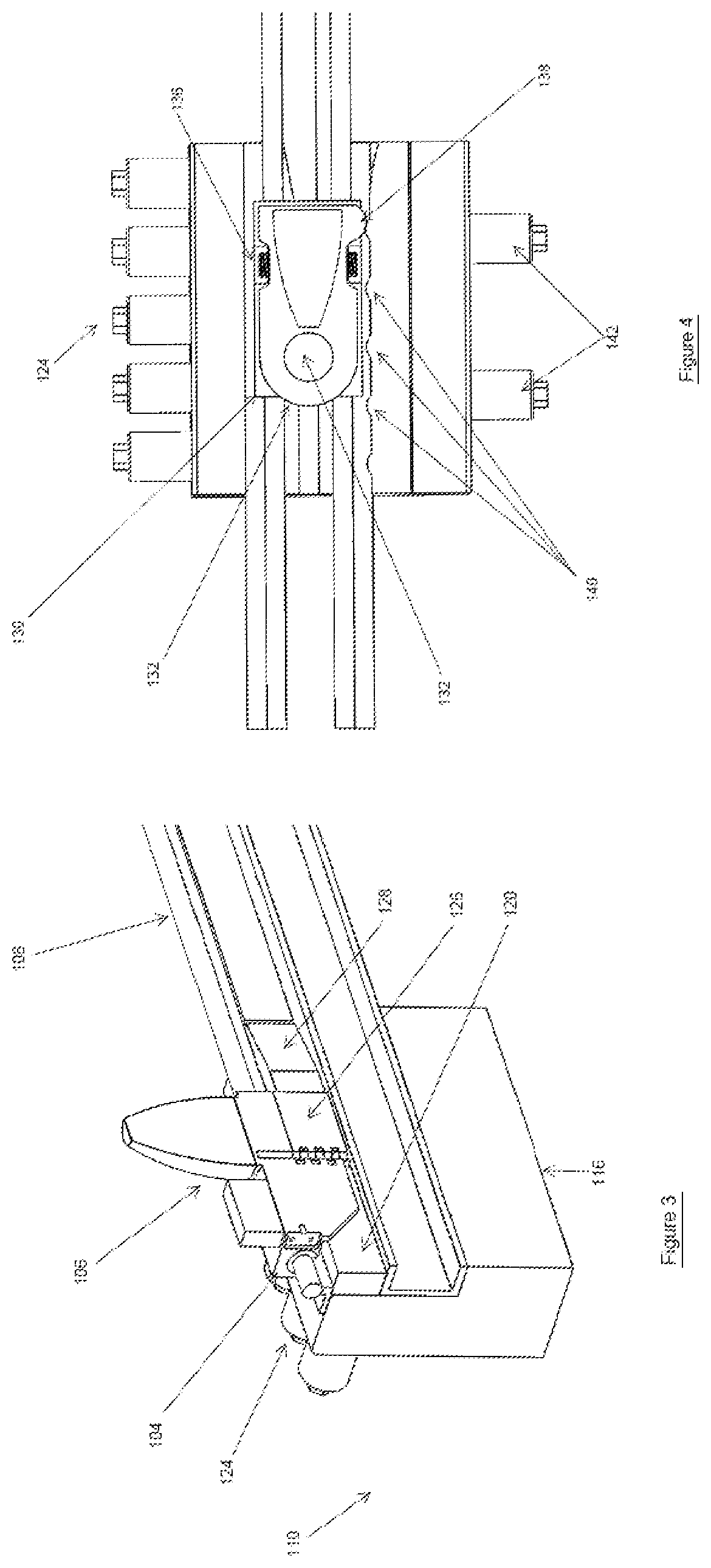
[0054]The shock testing machine of the first embodiment is shown in FIG. 1, generally referred to by reference numeral 100. In FIG. 1, the breaks on the left and right of the machine are used to denote a long length of the components being broken. In this design, the machine 100 is laid down horizontally to allow the use of longer test platform travel and the use of longer length bungee cords 102 to provide large accelerating forces to the test platform 104 over the entire range of its travel. The test objects 106 are mounted over the test platform 104 using mounting means specific to the type of object and the testing required. The test platform 104 is accelerated on one or more guide rails 108 towards a braking station 110 having braking elements (described below) by locking the test platform 104 from movement, tensioning the bungee cords 102 with the bungee tensioning cable 112 and winch 114 and then releasing the test platform 102 to allow the tension in the bungee cord(s) 102 t...


PUM


Abstract

A brake for use with a shock testing machine, the brake including: a brake material for generating a frictional force to stop a test platform when the brake material is urged against an opposed braking surface; links for rotatably connecting the brake material to the test platform; a biasing spring to bias the brake material towards the braking surface; a restraint mechanism for restraining the braking material, against a biasing force of the biasing spring, in a retracted position where the braking material is separated from the braking surface; and a release mechanism for releasing the restraint of the release mechanism to bias the brake material against the braking surface; wherein the links are configured such that relative movement between the brake material and braking surface while the brake material and braking surface are engaged causes a frictional force between the brake material and braking material to increase.

Description

CROSS REFERENCE TO RELATED APPLICATIONS[0001]This application is a continuation-in-part application of U.S. patent application Ser. No. 15 / 058,057 filed on Mar. 1, 2016, which claims benefit to U.S. Provisional Application No. 62 / 129,791 filed on Mar. 7, 2015, the contents of which is incorporated herein by reference.BACKGROUND1. Field[0002]The present invention relates generally to high-G shock testing machines, and more particularly to low-cost, reusable, “pseudo-static” testing machines and methods capable of imposing high acceleration and deceleration (>±10,000 g), opposing loads to a large (10-100+ lbs.) payload that are sustained over long durations (>5 msec). Such machine would provide the means for testing ordnance and commercial products / components under multi-axial loading, which includes both bending and shear moments. This includes the most extreme example of such events, namely “tail slap”, where large lateral accelerations are introduced due to the bending and re...

Claims


Application Information

Patent Timeline
IPC IPC(8): G01N3/307F16D65/18G01M7/08
CPCG01M99/004F16D65/18G01M7/08G01N3/307B60T1/14B61H7/12F16D63/008F16D65/22F16D2125/66
Inventor FISCHER, JACQUESRASTEGAR, JAHANGIR S
Owner OMNITEK PARTNERS LLC
Why Eureka
Try Eureka