System and method for dynamic multiple contrast enhanced, magnetic resonance fingerprinting (dmce-mrf)

a dynamic multiple contrast and fingerprinting technology, applied in image enhancement, nmr measurement, instruments, etc., can solve the problems of limiting the molecular limiting the mri studies to one contrast agent at a time, and making the analysis shown in fig. 1 even more problemati

Active Publication Date: 2020-02-06
CASE WESTERN RESERVE UNIV
View PDF0 Cites 8 Cited by
  • Summary
  • Abstract
  • Description
  • Claims
  • Application Information

AI Technical Summary

Benefits of technology

[0014]The present disclosure addresses the aforementioned drawbacks by providing systems and methods for dynamic, multiple, contrast-enhanced imaging studies of a patient using magnetic resonance fingerprinting (MRF). That is, the present disclosure provides systems and methods to perform dynamic, multi-contrast-enhanced MRF (DMCE-MRF) or dynamic, dual-contrast-enhanced MRF (DDCE-MRF). As such, multiple molecular MRI contrast ag

Problems solved by technology

However, a key limitation for current clinical MRI approaches is that MRI images are typically constrained to providing qualitative, diagnostic images that require subjective image interpretation.
However, each paramagnetic MRI contrast agent alters both the T1 and T2 relaxation times thereby limiting these molecular MRI studies to one contrast agent at a time.
It is also important to note that disease typically exhibits temporal and spatial heterogeneity in individuals, especially in human disease, making the analyses shown in FIG. 1 even more problematic.
Unfortunately, detecting non-proton-based contrast agents with traditional MRI imaging techniques is time-consuming and suffers from significant reductions in sensitivity.
Multinuclear MRI capabilities adds significant cost for specialized MRI hardware, such as special RF coils that are tuned to each nuclei.
Such specialized MRI hardware and the software to operate the MRI system with specialized hardware in this manne

Method used


Image

  • System and method for dynamic multiple contrast enhanced, magnetic resonance fingerprinting (dmce-mrf)
  • System and method for dynamic multiple contrast enhanced, magnetic resonance fingerprinting (dmce-mrf)
  • System and method for dynamic multiple contrast enhanced, magnetic resonance fingerprinting (dmce-mrf)

Examples


Embodiment Construction

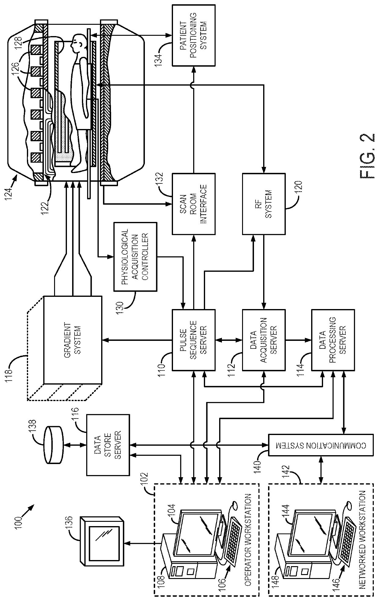
[0025]Referring particularly now to FIG. 2, an example of an MRI system 100 that can implement the methods described here is illustrated. The MRI system 100 includes an operator workstation 102 that may include a display 104, one or more input devices 106 (e.g., a keyboard, a mouse), and a processor 108. The processor 108 may include a commercially available programmable machine running a commercially available operating system. The operator workstation 102 provides an operator interface that facilitates entering scan parameters into the MRI system 100. The operator workstation 102 may be coupled to different servers, including, for example, a pulse sequence server 110, a data acquisition server 112, a data processing server 114, and a data store server 116. The operator workstation 102 and the servers 110, 112, 114, and 116 may be connected via a communication system 140, which may include wired or wireless network connections.

[0026]The pulse sequence server 110 functions in respon...


PUM


Abstract

The present disclosure provides a method of DDCE-MRF. The method can include: a) introducing two or more contrast agents to a region of interest (ROI) of a subject, the two or more contrast agents having different relaxivities; b) measuring a T1 relaxation time and a T2 relaxation time for locations within the ROI using magnetic resonance fingerprinting (MRF); c) determining, using equations that relate the different relaxivities, the T1 relaxation time, the T2 relaxation time, and concentrations of the two or more contrast agents, the concentrations of the two or more contrast agents for each of the locations within the ROI; and d) producing an image depicting the ROI based, at least in part, on the concentrations of the two or more contrast agents.

Description

CROSS-REFERENCE TO RELATED APPLICATIONS[0001]The present application is based on, claims priority to, and incorporates herein by reference in its entirety for all purposes, U.S. Provisional Application Ser. No. 62 / 482,755, filed Apr. 7, 2017, and entitled, “SYSTEM AND METHOD FOR DYNAMIC DUAL CONTRAST ENHANCED—MAGNETIC RESONANCE FINGERPRINTING (DDCE-MRF).”STATEMENT REGARDING FEDERALLY SPONSORED RESEARCH[0002]This invention was made with government support under R01 DK085099 and R21 HL130839 awarded by the National Institutes of Health. The government has certain rights in the invention.BACKGROUND[0003]Conventional magnetic resonance imaging (“MRI”) pulse sequences include repetitive similar preparation phases, waiting phases, and acquisition phases that serially produce signals from which images can be made. The preparation phase determines when a signal can be acquired and determines the properties of the acquired signal. For example, a first pulse sequence may produce a T1-weighted...

Claims


Application Information

Patent Timeline
IPC IPC(8): G01R33/50A61B5/055G01R33/56G06T7/00G01R33/48
CPCG01R33/5601G06T7/0016G01R33/4828A61B5/055G01R33/50G01R33/5602G06T2207/10096A61K49/101G06T2207/30016A61B5/7207A61B5/113A61B5/7289G01R33/5635G01R33/5608
Inventor FLASK, CHRISANDERSON, CHRISTIANYU, XINSTEINMETZ, NICOLEGRISWOLD, MARK A.BRADY-KALNAY, SUSANN
Owner CASE WESTERN RESERVE UNIV
Why Eureka
Try Eureka