Rapid pulse electrohydraulic (EH) shockwave generator apparatus with improved acoustic wavefronts

a technology of electrohydraulic shockwave generator and rapid pulse, which is applied in the field of therapeutic uses of shock waves or shockwaves, can solve the problems of large ttpt, unfavorable treatment needs, and unpredictable potential damage to tissue from shockwaves between 1 hz and 10 hz, so as to reduce tissue damage and pain, improve acoustic wavefront, and improve the effect of acoustic therapy

Pending Publication Date: 2020-02-13
SOLITON
View PDF6 Cites 2 Cited by
  • Summary
  • Abstract
  • Description
  • Claims
  • Application Information

AI Technical Summary

Benefits of technology

[0023]This disclosure includes embodiments of apparatuses and methods for electrohydraulic generation of rapid acoustic pulses with improved acoustic wavefronts. In certain embodiments, these improved acoustic wavefronts comprise an essentially planar acoustic wavefront in the near field of the targeted treatment area that quickly disperses after a defined distance. Such a wavefront provides effective acoustic therapy in the targeted area, while limiting tissue damage and pain beyond the targeted area. In another embodiment, the improved acoustic wavefront comprises an essentially planar non-focused acoustic wavefront in the near field of the targeted treatment area that quickly disperses after a defined distance, where the acoustic wavefront is essentially uniform in terms of peak pressure. Such a wavefront provides effective acoustic therapy in the targeted areas that minimizes high concentrations of peak pressure (i.e., “hotspots”) and low concentrations of peak pressure (i.e., “shadows”). These essentially uniform, non-focused, acoustic wavefronts provide for more consistent therapy over a targeted treatment area.

Problems solved by technology

Prior art literature has indicated that faster pulse rates using EH systems to provide shockwaves can lead to tissue damage.
As a result, potential damage to tissue from shockwaves at PRs between 1 Hz and 10 Hz is unpredictable when typical lithotripsy power levels are used.
When, as may be typical, a treatment requires repositioning of a device at multiple treatment sites, the TTPT becomes large and potentially impractical for many patients and treatment needs.
While long treatment times may be acceptable for extracorporeal shockwave lithotripsy, the use of shockwaves to provide non-lithotripsy therapeutic effects on tissue in the medical setting is less than optimal if not impractical.
For example, the cost of treatment often increases with the time needed to administer a treatment (e.g., due to the labor, facilities and other resource costs allocated to the administration of the treatment).
Furthermore, in addition to costs, at some point the duration of providing treatment to the patient becomes unbearable for the patient receiving, and healthcare staff providing, the treatment.
However, parabolic reflectors can also present challenges.
First, when the tissue targeted for treatment is shallow (e.g., dermis of the skin), the peak pressure of the planar wave persists beyond the targeted tissue when using parabolic reflectors.
Such waves can result in unwanted damaging effects and pain at distant tissue sites beyond the targeted treatment sites.
For example, when treating dermis, a relatively planar wave will maintain enough peak pressure to effect the underlying bone structures resulting in significant pain to the patient.
Second, planar acoustic waves generated through the use of a parabolic reflector in an electrohydraulic shockwave generator are often not uniform.
This non-uniformity in the acoustic wavefront has at least two major sources: (1) aberrant acoustic wave reflections generated within the chamber; and (2) instability of the electrode gap location within the chamber.
These aberrant reflections will often result in the formation of acoustic wavefronts that have areas of higher peak pressures and lower peak pressures.
The instability of the electrode gap location within the chamber results from the pair of electrodes that produce a spark in the gap between the electrodes in electrohydraulic shockwave generators.
However, non-uniformity of the acoustic wavefront can occur when the focal location (“f location” or “focal point location”) of the electrode gap changes.
This convergence of these pressure lines will result in a peak pressure hotspot 204 deeper in the tissue, resulting in excess tissue damage, treatment discomfort, and pain.
The convergence of the pressure lines around the circumference of the treatment area will result in a peak pressure hotspot 204 deeper in the tissue, resulting in excess tissue damage, treatment discomfort, and pain.
Therefore, while the use of parabolic reflectors may produce stable acoustic waves in select treatment situations, due to acoustic wave peak pressure persistence and acoustic wave non-uniformity (i.e., hotspots and shadows), prior art approaches are less than optimal in consistently providing uniform acoustic wavefronts.
As a result, these acoustic wavefront persistence and hotspots can result in treatments that are both painful and harmful to the patient.
Designing free-form reflectors for illumination is difficult.

Method used


Image

  • Rapid pulse electrohydraulic (EH) shockwave generator apparatus with improved acoustic wavefronts
  • Rapid pulse electrohydraulic (EH) shockwave generator apparatus with improved acoustic wavefronts
  • Rapid pulse electrohydraulic (EH) shockwave generator apparatus with improved acoustic wavefronts

Examples


example

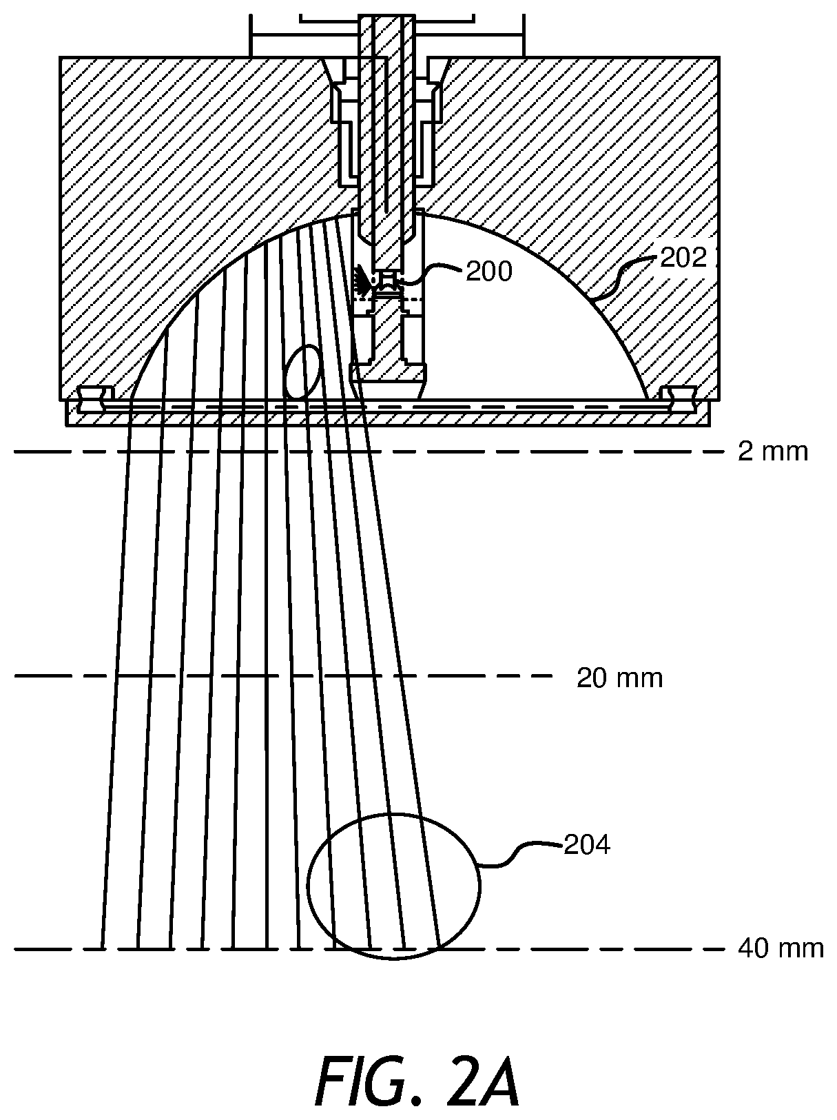
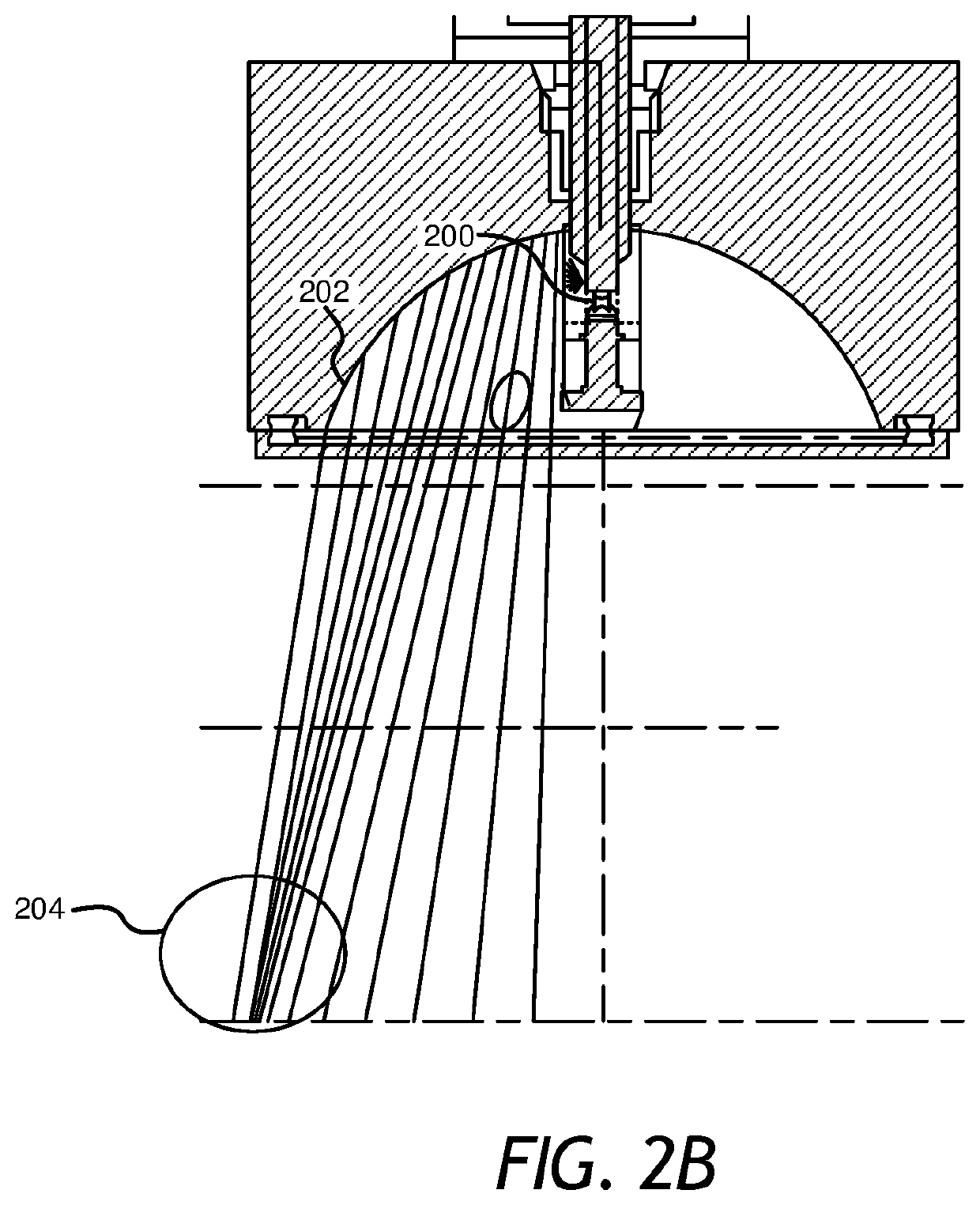
[0077]FIG. 10 depicts a cross-sectional drawing of one embodiment of an apparatus for electrohydraulic generation of acoustic waves that have improved acoustic wavefronts. As shown in FIG. 10, the apparatus 1000 for electrohydraulic generation of acoustic waves comprises: a housing 1004 defining a chamber 1008 and a shockwave outlet 1012; a liquid disposed in the chamber 1008; an acoustic reflector 1020 within the chamber 1008; a plurality of electrodes 1016a, 1016b (e.g., in the spark head or module) configured to be disposed in the chamber 1008 to define one or more spark gaps 200; and a pulse generation system configured to apply voltage pulses to the electrodes 1016a, 1016b at a rate of between 10 Hz and 5 MHz. In the embodiment shown, acoustic reflector 1020 is or comprises a free-form reflector, while in other embodiments, the acoustic reflector may be parabolic.

[0078]In this embodiment, a stabilized acoustic wavefront is achieved using a free-form acoustic reflector that has ...


PUM


Abstract

Apparatuses and methods for generating therapeutic compressed acoustic waves (e.g., shock waves) with an improved acoustic wavefront. In the apparatuses, a housing is defined by a chamber and a shockwave outlet, the chamber is configured to be filed with liquid, a plurality of electrodes defining one or more spark gaps and an acoustic reflector can disposed in the chamber, and a pulse generation system configured to apply voltage pulses to the electrodes at a rate of between 10 Hz and 5 MHz. The improved acoustic wavefront is achieved via a free-form acoustic reflector and / or a stable spark gap location. The free-form acoustic reflector is designed according to a disclosed method including iterating reflector shape using spline interpolation based on defined variables. Additionally, a stable spark gap location is achieved via a single servomotor that adjusts both electrodes simultaneously.

Description

[0001]This application claims benefit of priority to U.S. Provisional Patent Application Ser. No. 62 / 447,191 filed Jan. 17, 2017, which is incorporated herein by reference in its entirety.BACKGROUND1. Field of the Invention[0002]The present invention relates generally to therapeutic uses for shock waves or shockwaves. More particularly, but not by way of limitation, the present disclosure relates to an apparatus and method for generating therapeutic shock waves or shockwaves (shock waves with therapeutic uses) with improved acoustic wavefronts.2. Description of Related Art[0003]Acoustic shockwaves have been used for certain therapies for a number of years. “Shock wave” or “shockwave” is generally used to refer to an acoustic phenomenon (e.g., resulting from an explosion or lightning) that creates a sudden and intense change in pressure. These intense pressure changes can produce strong waves of energy that can travel through elastic media such as air, water, human soft tissue, or ce...

Claims


Application Information

Patent Timeline
Patent Type & Authority Applications(United States)
IPC IPC(8): A61B17/225G10K11/28G10K15/04
CPCG10K11/28A61B17/225G10K15/043A61B2017/22024G10K11/352A61B17/22012A61B2017/22025A61B2017/00017A61B2017/00398
Inventor CAPELLI, CHRISTOPHER C.PALMER, JEREMIAHSHAJII, ALIMASSE, DANIELKLEMP, WALTERROBERTSON, DAVIDCROWLEY, ROBERT
Owner SOLITON
Why Eureka
Try Eureka