Vehicle underbody structure

a technology for underbody and vehicle, applied in the direction of battery/cell propulsion, electric propulsion mounting, vehicle sub-unit features, etc., can solve the problems of increasing the air resistance of the vehicle underbody, reducing the aerodynamic performance of the vehicle, and reducing the height of the vehicle, so as to achieve the effect of improving the aerodynamic performance of the underfloor, reducing the formation of uneven parts, and improving the aerodynamic performan

Active Publication Date: 2020-02-13
TOYOTA JIDOSHA KK
View PDF0 Cites 10 Cited by
  • Summary
  • Abstract
  • Description
  • Claims
  • Application Information

AI Technical Summary

Benefits of technology

[0023]According to the vehicle underbody structure of the second aspect of the disclosure, the vehicle underbody structure has the superior effect that the formation of uneven portions can be reduced in a wide range of the vehicle undersurface and the aerodynamic performance of the underfloor can be further improved.
[0024]According to the vehicle underbody structure of the third aspect of the disclosure, the vehicle underbody structure has the superior effect that the battery can be protected from the load input to the vehicle body at the time of an impact to the vehicle.
[0025]According to the vehicle underbody structure of the fourth aspect of the disclosure, the vehicle underbody structure has the superior effect that space for mounting the fuel tank under the rear seat or the luggage compartment on the vehicle rear side can be ensured and the tank capacity can be sufficiently ensured.
[0026]According to the vehicle underbody structure of the fifth aspect of the disclosure, the vehicle underbody structure has the superior effect that the length of the high-voltage cable can be shortened and current loss between the battery and the inverter can be inhibited because the distance between the battery and the inverter is short.
[0027]According to the vehicle underbody structure of the sixth aspect of the disclosure, the vehicle underbody structure has the superior effect that the aerodynamic performance of the underfloor of a hybrid vehicle can be improved and at the same time the vehicle height can be reduced.
[0028]According to the vehicle underbody structure of the seventh aspect of the disclosure, the vehicle underbody structure has the superior effect that the aerodynamic performance of the underfloor of a fuel cell vehicle can be improved and at the same time the vehicle height can be reduced.

Problems solved by technology

However, in the related art described above, uneven portions are formed in the undersurface of the vehicle by vehicle body members mounted to the lower side of the floor panel and the air resistance of the vehicle underbody increases, whereby the aerodynamic performance of the vehicle is reduced.
Furthermore, when the height from the road surface to the vehicle undersurface is ensured, it becomes difficult to reduce the vehicle height.
As a result, current loss between the battery and the inverter is inhibited.

Method used


Image

  • Vehicle underbody structure
  • Vehicle underbody structure
  • Vehicle underbody structure

Examples


first embodiment

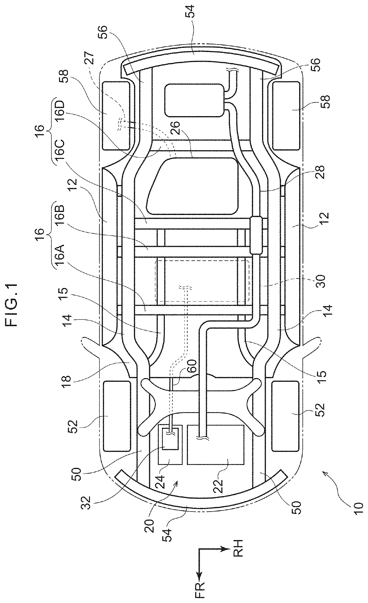
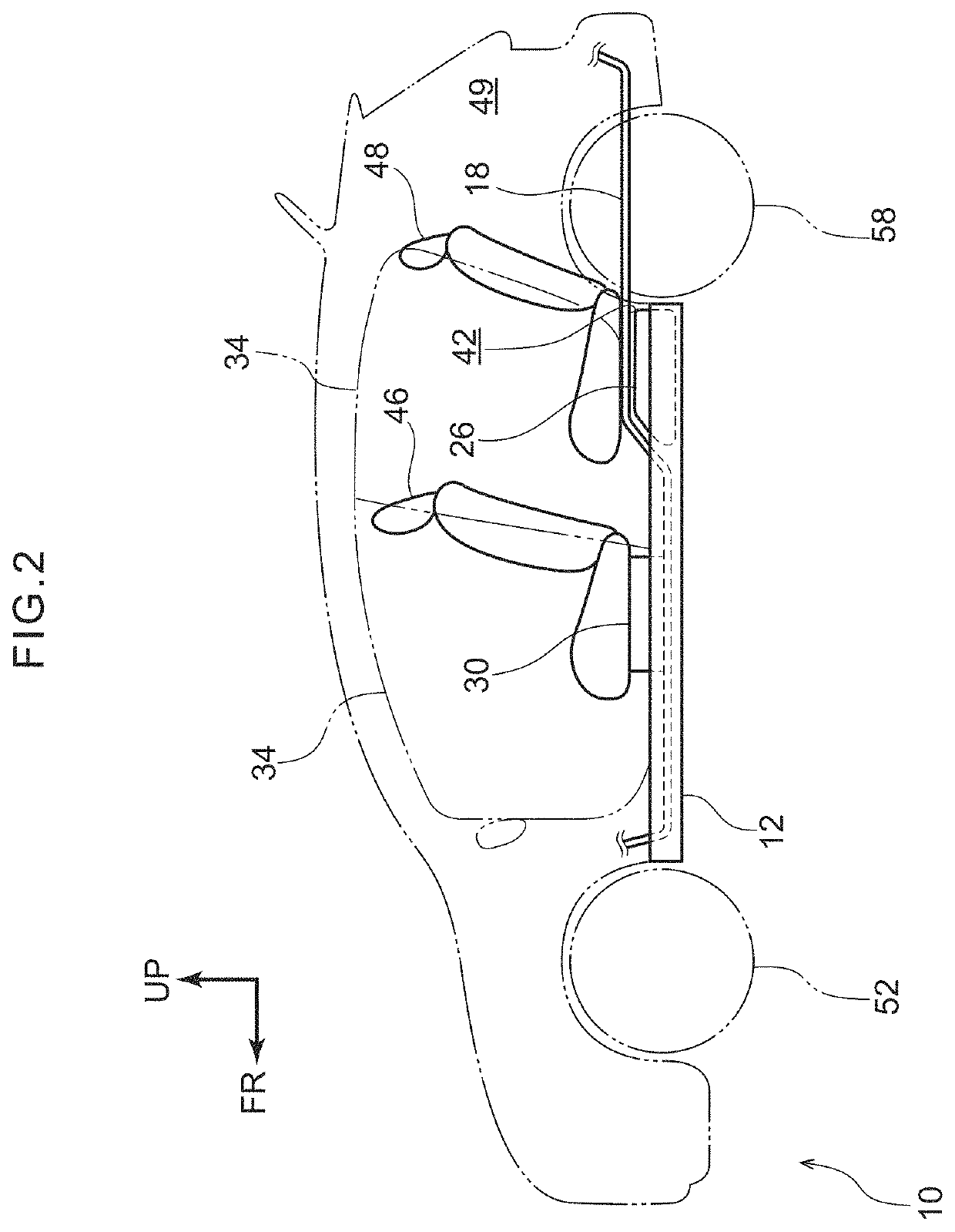
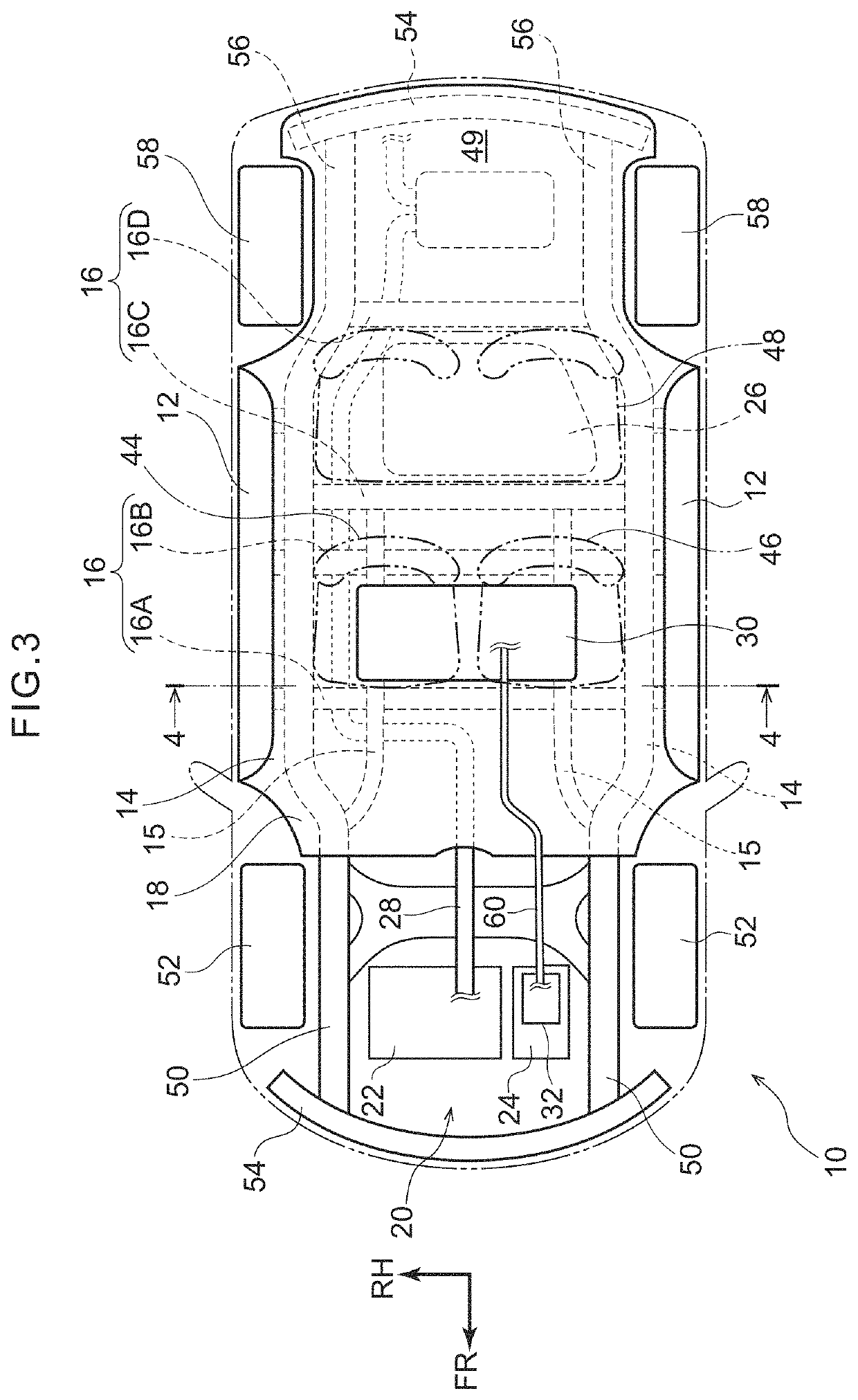
[0036]A first embodiment of a vehicle underbody structure pertaining to the disclosure will be described below on the basis of FIG. 1 to FIG. 4. It will be noted that, for convenience of description, arrow UP appropriately shown in the drawings indicates a vehicle body upward direction, arrow FR indicates a vehicle body forward direction, and arrow RH indicates a rightward direction in the vehicle width direction. Furthermore, when the directions of upper / lower, front / rear, and right / left are used with further specification in the following description, these will be understood to mean upper / lower in the vehicle body up and down direction, front / rear in the vehicle body front-rear direction, and right / left in the vehicle body right and left direction (the vehicle width direction). Furthermore, there are cases where some reference signs are omitted in the drawings to make it easier to see what is shown in the drawings.

[0037]FIG. 1 is a bottom view showing a vehicle underbody of a veh...

second embodiment

[0071]Next, a vehicle 70 to which a vehicle underbody structure pertaining to a second embodiment has been applied will be described on the basis of FIG. 5 and FIG. 6. It will be noted that parts that are the same as those in the first embodiment are assigned the same reference signs, and detailed description (also including shared action) will be appropriately omitted. The vehicle 70 pertaining to the second embodiment differs from the vehicle 10 pertaining to the first embodiment in that it is a fuel cell vehicle, and hydrogen tanks 72 are mounted to the vehicle underbody.

[0072]As shown in these drawings, the vehicle 70 has, as a drive source, the traveling motor 24 in the drive unit 20 provided in the vehicle front portion. The traveling motor 24 is driven by optimally separately using electric power supplied from two energy sources, a fuel cell (FC) stack 74 and a battery 76.

[0073]Specifically, electric energy and water are produced by a chemical reaction between oxygen and hydr...


PUM


Abstract

A vehicle underbody structure includes a pair of rockers that are provided on both vehicle width direction sides of a vehicle underbody and extend in a vehicle front-rear direction, a battery that is disposed centrally in a vehicle width direction center between the pair of rockers and is disposed above a vehicle floor and on the lower side of a seat, a fuel tank that is disposed in the vehicle width direction center between the pair of rockers and is disposed under the vehicle floor and further toward a rear side of the vehicle than the battery, and a waste pipe that is coupled to a drive unit provided at a vehicle front side of the battery and extends in the vehicle front-rear direction between the battery and one of the rockers.

Description

CROSS-REFERENCE TO RELATED APPLICATION[0001]This application is based on and claims priority under 35 USC 119 from Japanese Patent Application No. 2018-150691 filed on Aug. 9, 2018, the disclosure of which is incorporated by reference herein.BACKGROUNDTechnical Field[0002]The present disclosure relates to a vehicle underbody structure.Related Art[0003]Japanese Patent Application Laid-open (JP-A) No. 2017-081211 discloses a vehicle underbody structure where side sills (rockers) that extend along the vehicle front-rear direction are provided on both right and left sides of a vehicle underbody and where a hydrogen tank, a battery, and an exhaust gas pipe are disposed on the lower side of a floor panel that bridges the side sills.[0004]However, in the related art described above, uneven portions are formed in the undersurface of the vehicle by vehicle body members mounted to the lower side of the floor panel and the air resistance of the vehicle underbody increases, whereby the aerodyna...

Claims


Application Information

Patent Timeline
Patent Type & Authority Applications(United States)
IPC IPC(8): B62D21/02B62D35/02B60K15/07B60K1/04B60L50/60B62D21/15B60L50/64B62D25/20
CPCB60K2001/0438B60K15/07B60L50/66B60L50/64B60K1/04B62D21/157B62D25/20B60K2015/03118B62D21/02B60Y2306/01B62D35/02B60K13/04B60K15/067B60K2015/03315B62D25/2018B62D25/2036B62D25/2027B62D25/2009B60L50/61B60K2001/0422B60K15/063B60K2015/0634B60K2015/0633B60K15/03006Y02T10/62Y02T10/70
Inventor AJISAKA, SATOSHI
Owner TOYOTA JIDOSHA KK
Why Eureka
Try Eureka