Eureka AIR delivers breakthrough ideas for toughest innovation challenges, trusted by R&D personnel around the world.

Direct fuel injection, two-valve per cylinder pushrod valvetrain combustion system for an internal combustion engine

Active Publication Date: 2020-02-20
GM GLOBAL TECH OPERATIONS LLC
View PDF3 Cites 1 Cited by
  • Summary
  • Abstract
  • Description
  • Claims
  • Application Information

AI Technical Summary

Benefits of technology

The patent describes a pushrod valvetrain system for an internal combustion engine that includes a cylinder head with a single intake and exhaust port and a two-valve pushrod assembly. The system also includes a plurality of cylinder tops and pushrod assemblies that align with different engine cylinders. The system includes a camshaft and rocker arms that drive the intake and exhaust valves, as well as a fuel injector and spark plug for each cylinder. The intake and exhaust ports are positioned adjacent each other and are positioned along an axis that intersects the center point of each port. The technical effects of the invention include improved fuel injection and ignition timing, reduced emissions, improved engine performance, and simplified design.

Problems solved by technology

Typical internal combustion engines of the above-noted type have limited overhead room for the spark plug and fuel injector due to the space taken up by the pushrod and rocker arms.
This arrangement can limit the ability to achieve optimal combustion dynamics, as it spaces the spark plug farther away from the injector than may be desired and requires these components to be oriented more horizontally within the combustion chamber than may be desired.

Method used


Image

  • Direct fuel injection, two-valve per cylinder pushrod valvetrain combustion system for an internal combustion engine
  • Direct fuel injection, two-valve per cylinder pushrod valvetrain combustion system for an internal combustion engine
  • Direct fuel injection, two-valve per cylinder pushrod valvetrain combustion system for an internal combustion engine

Examples


Embodiment Construction

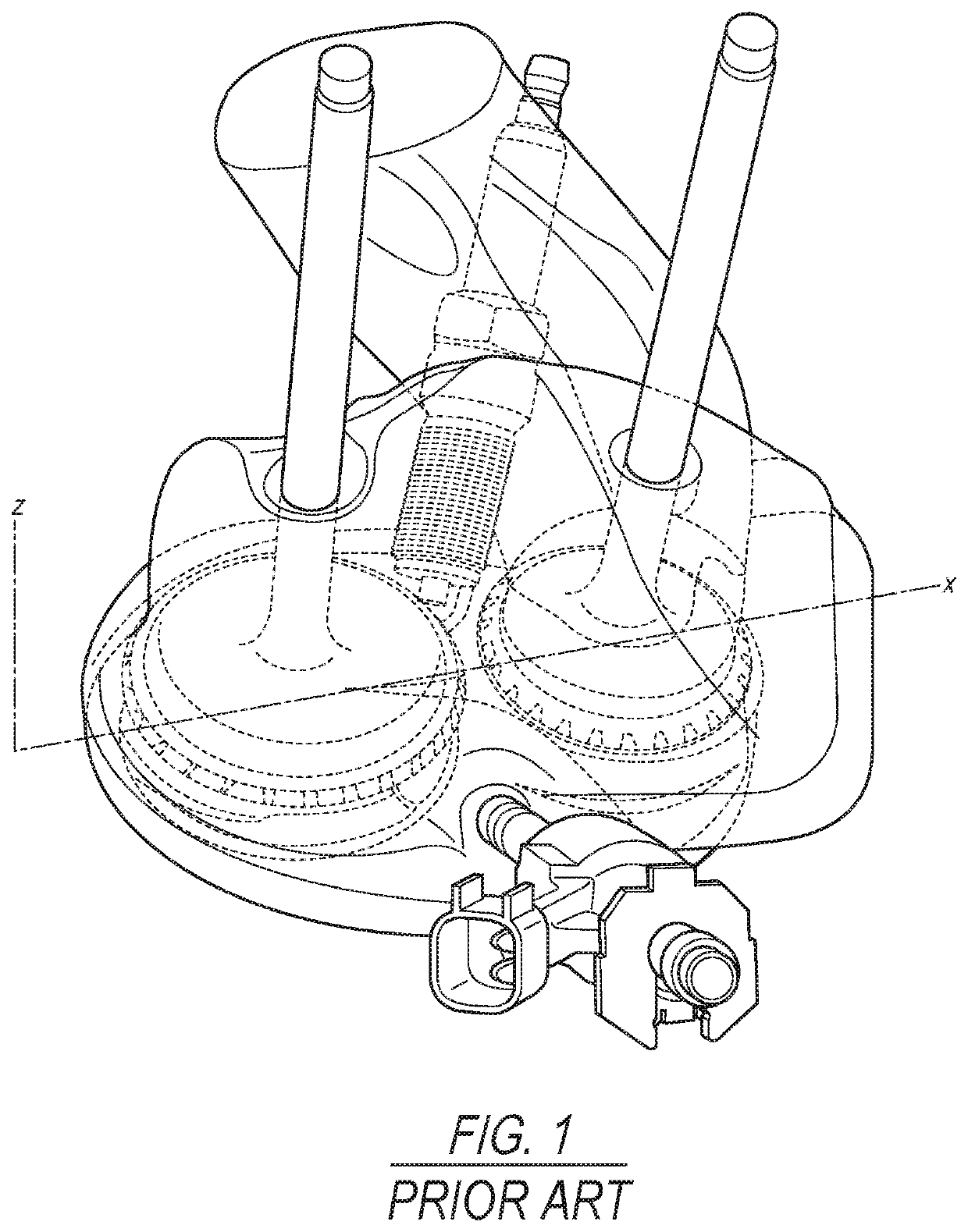
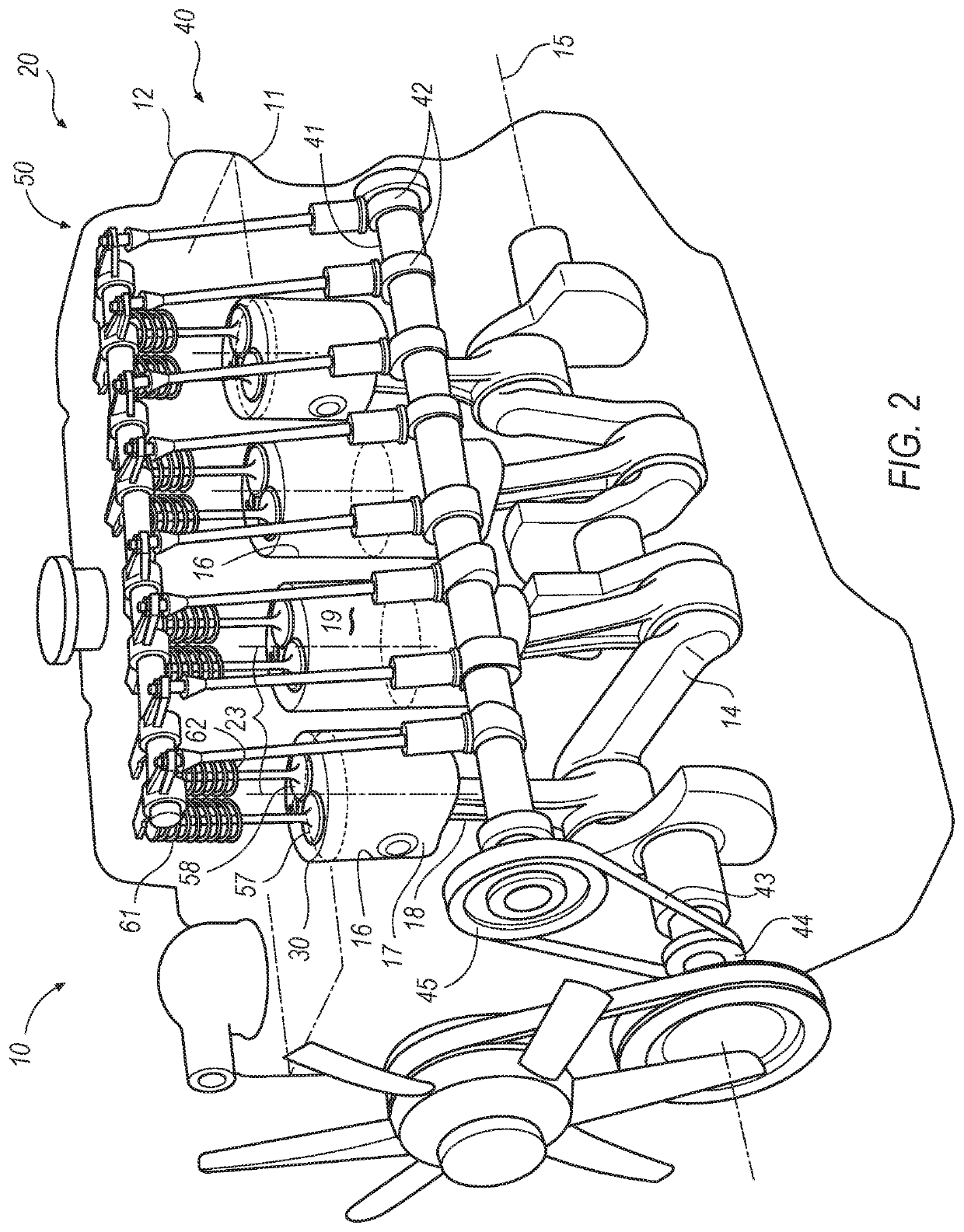
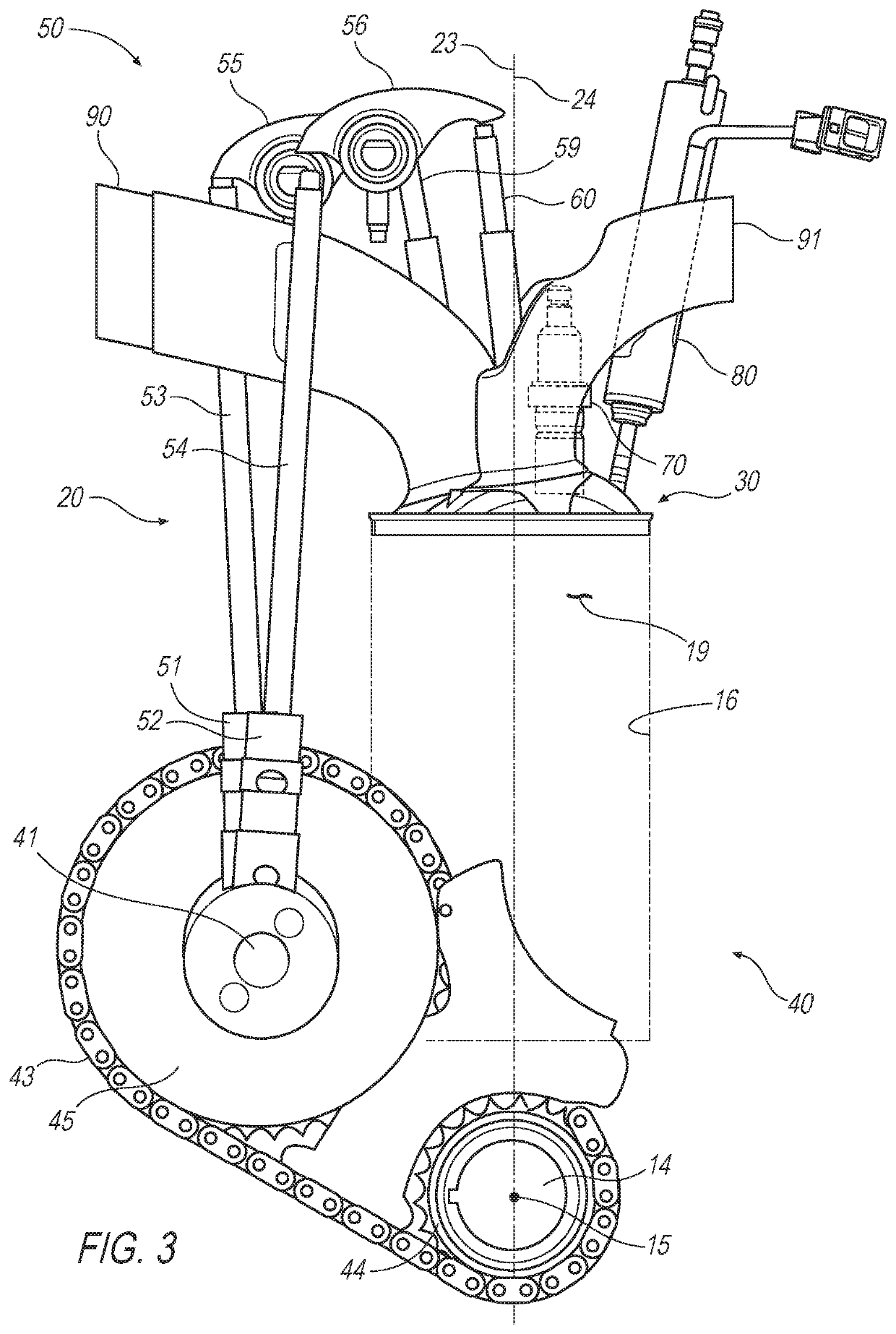
[0038]Described below and shown in the accompanying drawings is an embodiment of a direct fuel injection, two-valve per cylinder pushrod valvetrain internal combustion engine having a unique cylinder head design that provides near vertical orientation of the spark plug and fuel injector at a more central location of the cylinder on a single (exhaust) side of the valves. This configuration enables new flexibility in combustion system design, potentially providing for improved fuel economy and drive quality due to enhanced air / fuel mixing that results from the more vertical orientation of the injector and / or spark plug, and from the close positioning of the spark plug to the fuel injector nozzle. As will be appreciated by those skilled in the art, these characteristics of the disclosed design can enable late fuel injection during the combustion cycle, thereby allowing for increased compression ratio due to faster combustion speed, as well as improved knock characteristics and combusti...


PUM


Abstract

A pushrod valvetrain combustion system assembly for an internal combustion engine includes a two-valve pushrod assembly and a cylinder top that forms a portion of a cylinder head. The cylinder top has a single intake port, a single exhaust port, a spark plug bore, and a fuel injector bore. The pushrod assembly includes an intake valve positioned in the intake port and an exhaust valve positioned in the exhaust port. The intake port and exhaust port are positioned adjacent each other and are positioned along an axis that intersects a center point of each of the ports. The intersecting axis is rotated relative to a centerline of the crankshaft of the engine, providing space for the spark plug bore and fuel injector bore to both be located in the cylinder top on a same side of the intersecting axis.

Description

INTRODUCTION[0001]The present invention relates to direct fuel injection, two-valve per cylinder pushrod valvetrain combustion systems used in internal combustion engines.[0002]Typical internal combustion engines of the above-noted type have limited overhead room for the spark plug and fuel injector due to the space taken up by the pushrod and rocker arms. Consequently, in conventional designs the spark plug and fuel injector are positioned on opposite sides of the central plane of the cylinder, and at significant angles relative to the central axis of the cylinder. An example of this is shown in FIG. 1 showing a cylinder top in which intake and exhaust valves are centered on a vertical (x-z) plane that intersects with the crankshaft axis (not shown), thereby forming a conventional valve layout that is in-line with the crankshaft. A spark plug and fuel injector are mounted on opposite sides of that vertical plane at large angles relative to the plane. This arrangement can limit the ...

Claims


Application Information

Patent Timeline
IPC IPC(8): F02F1/24F01L1/14F02F7/00F02M61/14F02F1/42
CPCF02F2001/245F02F7/006F01L1/146F02M61/14F02F1/4285F02F1/242F01L1/14F01L1/18F01L2003/256F01L1/182F01L2001/054F01L2250/02
Inventor KEATING, EDWARD J.EASTMAN, KENNETH M.GAUTIER, ERWAN R.
Owner GM GLOBAL TECH OPERATIONS LLC
Why Eureka
Eureka Blog
Learn More