Check patentability & draft patents in minutes with Patsnap Eureka AI!

Solvent Recovery System

a solvent recovery and film evaporator technology, applied in the direction of evaporation, evaporator regulation/control, separation process, etc., can solve the problems of high labor-to-product cost, slow recovery rate, and large footprin

Inactive Publication Date: 2020-03-05
VAN LENTEN III RAYMOND
View PDF0 Cites 1 Cited by
  • Summary
  • Abstract
  • Description
  • Claims
  • Application Information

AI Technical Summary

Benefits of technology

The present invention relates to a solvent recovery system designed to efficiently recover ethanol and / or alcohol from large amounts of high-quality material. The system can operate at high output levels while reducing energy and staff requirements. It provides a recovery rate of up to 300 gallons per hour with an extremely low residence time and can be modified for custom applications. An improved feed system is provided which allows for more continuous flow of material and more efficient processing of material, as well as more efficient dispersal through the heat exchanger. The system can also provide a discharge system for the continuous discharge of the recovered solvents and residues from the system.

Problems solved by technology

For example, rotary evaporators have been the industry standard for low volume production due to their inexpensive costs.
However, these systems provide slow recovery rates and have large footprints and higher labor-to-output costs, which make these systems inefficient at higher levels of production.
While falling film evaporators allow for more efficient mass volume production, the feed systems of most falling film evaporators often limit the rate at which materials are fed into the falling film evaporator.
In consequence, the rate and efficiency at which solvents are recovered from a material stream over a length of time are limited.

Method used


Image

  • Solvent Recovery System
  • Solvent Recovery System
  • Solvent Recovery System

Examples


first embodiment

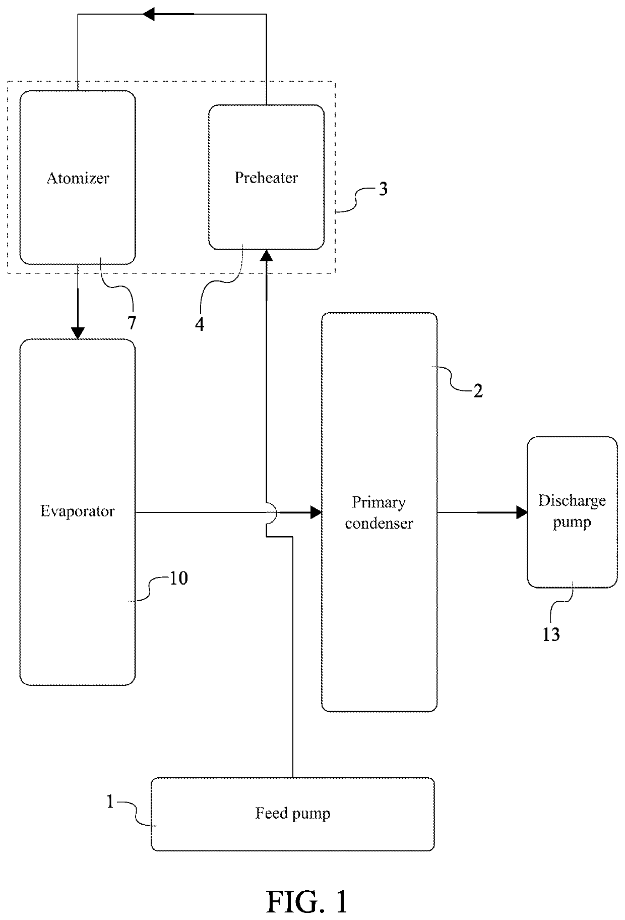
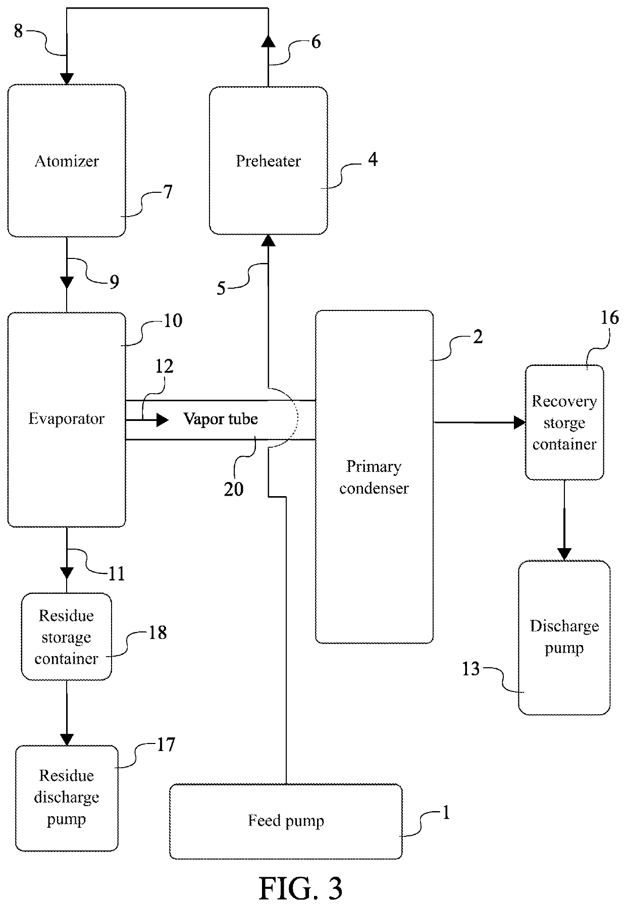
[0020]In the present invention and with reference to FIGS. 3 through 5, the heating system 3 comprises a preheater 4 and an atomizer 7 in order to heat the fluid. The preheater 4 is used to heat the fluid after being pushed through feed pump 1. After the fluid has been heated by the preheater 4, the atomizer 7 is used to superheat the fluid in order to emit the fluid as a fine spray. Further, the atomizer 7 is able to heat the fluid without boiling the liquid. The fluid is preferably heated to 180 degrees Fahrenheit after going through the preheater 4 and the atomizer 7. The preheater 4 comprises a first inlet 5 and a first outlet 6. The atomizer 7 comprises a second inlet 8 and a second outlet 9. The feed pump 1 is in fluid communication with the first inlet 5. In the preferred embodiment, a pipe or tube is used to establish the fluid communication between the feed pump 1 and the first inlet 5. This arrangement allows the fluid to flow from the feed pump 1 into the preheater 4. Fur...

second embodiment

[0027]Further in the present invention and with reference to FIGS. 6 through 9, the present invention may further comprise a three-way valve 21. The three-way valve 21 is a device used to divert flow of the fluid. In further detail, the three-way valve 21 in used for a “recycle” function of the present invention. Solvent may be trapped inside the preheater 4 after overall process of the present invention because the preheater 4 is filled from the bottom up. For maintenance and cleaning, the three-way valve 21 switches direction and the feed pump 1 spins backwards in order to send the trapped solvent to the atomizer 7 and then the evaporator 10 for reclaiming. The three-way valve 21 is in bidirectional fluid communication with the preheater 4 through the feed pump 1. This arrangement allows fluid to flow from the three-way valve 21 and into the preheater 4. Further, this allows trapped solvent to flow from the preheater 4 and back into the feed pump 1. The feed pump 1 is a conduit be...


PUM


Abstract

A solvent recovery system allows for a continuous recovery of ethanol, alcohol, or other solvent from an oil / material feed. The solvent recovery system includes a feed pump, a primary condenser, a heating system, an evaporator, a discharge pump, and a control system. The feed pump is used to drive a fluid which can be retrieved from an oil / material feed. The primary condenser is a device able to condense the fluid from a gas to liquid state through a cooling method. The heating system includes devices able to heat the fluid in order to prepare the fluid to change into a gas state. The evaporator is a device able to process the fluid from a liquid to gas state. The discharge pump is used to output ethanol, alcohol, or other solvent, recovered from the fluid. The control system allows a user manually or electronically manage and control the solvent recovery system.

Description

[0001]The current application claims a priority to the U.S. Provisional Patent application Ser. No. 62 / 724,509 filed on Aug. 29, 2018.FIELD OF THE INVENTION[0002]The present invention generally relates to falling film evaporators and solvent recovery systems. More specifically, the present invention relates to solvent recovery systems with integrated falling film evaporators adapted for efficient mass volume recovery applications.BACKGROUND OF THE INVENTION[0003]Solvent recovery systems involve processes where various materials in a mixed stream are retrieved from the stream to be reused for other processes. By recovering these reusable materials, the demand for raw materials is reduced which helps maintain costs down as well as meet various regulatory requirements, such as cleaning waste streams before disposal. Various solvent recovery systems have been provided for both large-scale and small-scale applications. For example, rotary evaporators have been the industry standard for l...

Claims


Application Information

Patent Timeline
IPC IPC(8): B01D1/00B01D1/06B01D1/30C10G31/06
CPCB01D1/0082C10G31/06B01D1/0064B01D1/30B01D1/065B01D1/00B01D1/16B01D5/0036B01D5/006
Inventor VAN LENTEN, III, RAYMOND
Owner VAN LENTEN III RAYMOND
Features
  • R&D
  • Intellectual Property
  • Life Sciences
  • Materials
  • Tech Scout
  • Unparalleled Data Quality
  • Higher Quality Content
  • 60% Fewer Hallucinations
Learn More