
Laser-induced Anti-corrosion micro-anchor structural layer for metal-polymeric composite joint and methods of manufacturing thereof

Inactive Publication Date: 2020-03-05
GM GLOBAL TECH OPERATIONS LLC
View PDF4 Cites 0 Cited by
  • Summary
  • Abstract
  • Description
  • Claims
  • Application Information

AI Technical Summary

Benefits of technology

The patent text describes a problem in manufacturing certain components in vehicles made from lightweight materials like aluminum and magnesium alloys, which can improve fuel efficiency but make it difficult to join multiple smaller components. There are also challenges in joining dissimilar materials like metal and reinforced polymeric composites, such as low initial strength and susceptibility to corrosion. The patent aims to develop a quick and robust method of joining these materials to form corrosion-resistant high-strength joints.

Problems solved by technology

While use of such lightweight materials can serve to reduce overall weight and generally improve fuel efficiency, issues can arise in manufacturing certain components.
For example, molding large, complex parts from a reinforced composite material may be difficult or infeasible.
However, joining dissimilar materials, such as a metal and a reinforced polymeric composite, may present additional challenges such as low initial strength, susceptibility to corrosion, and long cycle times in manufacturing.

Method used


Image

  • Laser-induced Anti-corrosion micro-anchor structural layer for metal-polymeric composite joint and methods of manufacturing thereof
  • Laser-induced Anti-corrosion micro-anchor structural layer for metal-polymeric composite joint and methods of manufacturing thereof
  • Laser-induced Anti-corrosion micro-anchor structural layer for metal-polymeric composite joint and methods of manufacturing thereof

Examples


example 1

7-Day Corrosion Testing

[0112]With reference to FIGS. 17-19B, a first, second, third, and fourth metal-polymeric composite assemblies (also referred to as first, second, third, and fourth samples) are prepared according to certain aspects of the present disclosure. The first and third samples each include a first component having a first surface with a layer disposed thereon. A body of the first component includes a first metallic composition and the layer includes a second metallic composition. The first metallic composition includes hot dip galvanized (HDG) low-carbon steel and the second metallic composition includes SS316 stainless steel. The second and fourth samples each include a first component having the first metallic composition and a sacrificial coating including zinc (e.g., HDG steel). The second and fourth samples do not have layers of the second metallic material. Each of the first, second, third, and fourth components includes a second component including a polymer an...

example 2

Cyclic Corrosion Testing

[0116]First and second sets of samples are prepared. Each of the samples of the first set includes a metal component including steel and a stainless steel 316 layer, and a composite component including Nylon 6 and carbon fibers. Each of the samples of the second set includes a metal component including steel having a sacrificial zinc coating (e.g., HDG steel), and a composite component including Nylon 6 and carbon fibers.

[0117]The samples undergo cycles of a salt spray and dry off. Each test cycle includes three stages: (1) an ambient stage at a first temperature of about 25° C.±3° C. and a first relative humidity of about 45%±10%; (2) a humid stage at a second temperature of about 49° C.±2° C. and a second relative humidity of about 10%; and (3) a dry-off stage at a third temperature of about 60° C.±2° C. and a third relative humidity of less than about 30%. Each stage is performed for a duration of about 8 hours, for a total cycle duration of about 24 hours...

example 3

Layer Analysis

[0119]With reference to FIGS. 21A-21C, the composition of a joint is analyzed. The joint 370 includes a metal component 372 including steel and a layer 374, and a composite component 376. Energy-dispersive X-ray spectroscopy (EDX), is used to determine a thickness of a layer 374. Referring to FIG. 21C, a first color 378 corresponds to carbon, a second color 380 corresponds to chromium, a third color 382 corresponds to iron, and a fourth color 384 corresponds to nickel. The percentages correspond to weight percent of each element. Element mapping, a composite of which is shown at FIG. 21B, is used to identify the layer 374. An average thickness 386 of the layer 374 is about 600 μm.


PUM

PropertyMeasurementUnit
Thicknessaaaaaaaaaa
Thicknessaaaaaaaaaa
Poweraaaaaaaaaa

Abstract

A method of forming a layer on a first component according to various aspects of the present disclosure includes melting a portion of a first metallic composition of the first component. The melting includes directing a laser beam toward a first surface of the first component. The method further includes depositing a second metallic composition on the first surface by directing a precursor including the second metallic composition toward an intersection of the first surface and the laser beam. The second metallic composition is galvanically more noble than the first metallic composition. The method further includes forming the layer on the first component by solidifying the first metallic composition and the second metallic composition. The first component is configured to be joined to a second component by engaging a plurality of micro-anchors defined on the layer with a polymer of the second component.

Description

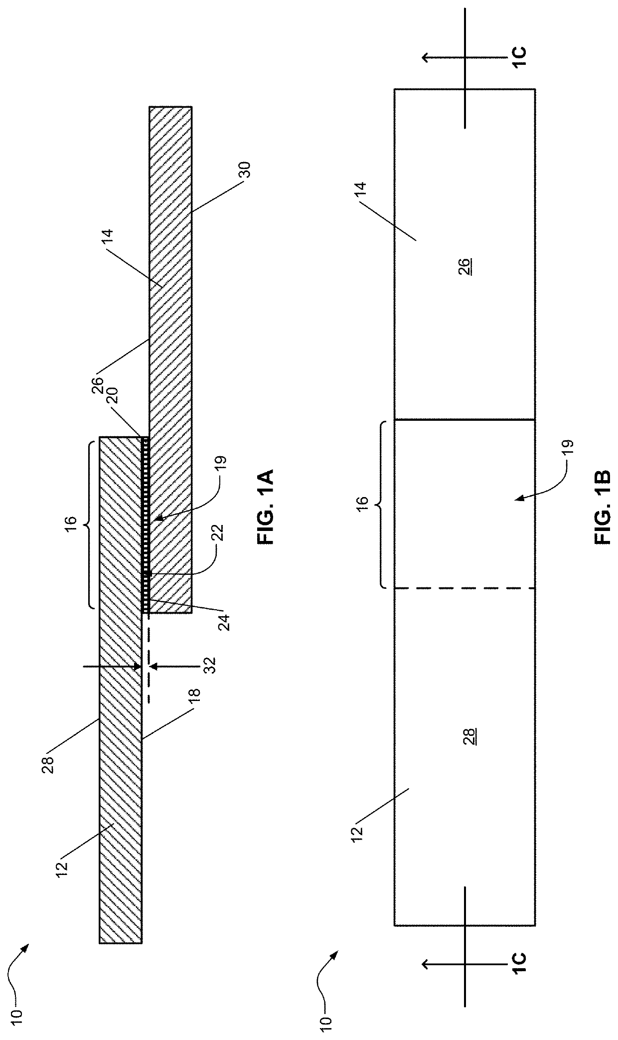
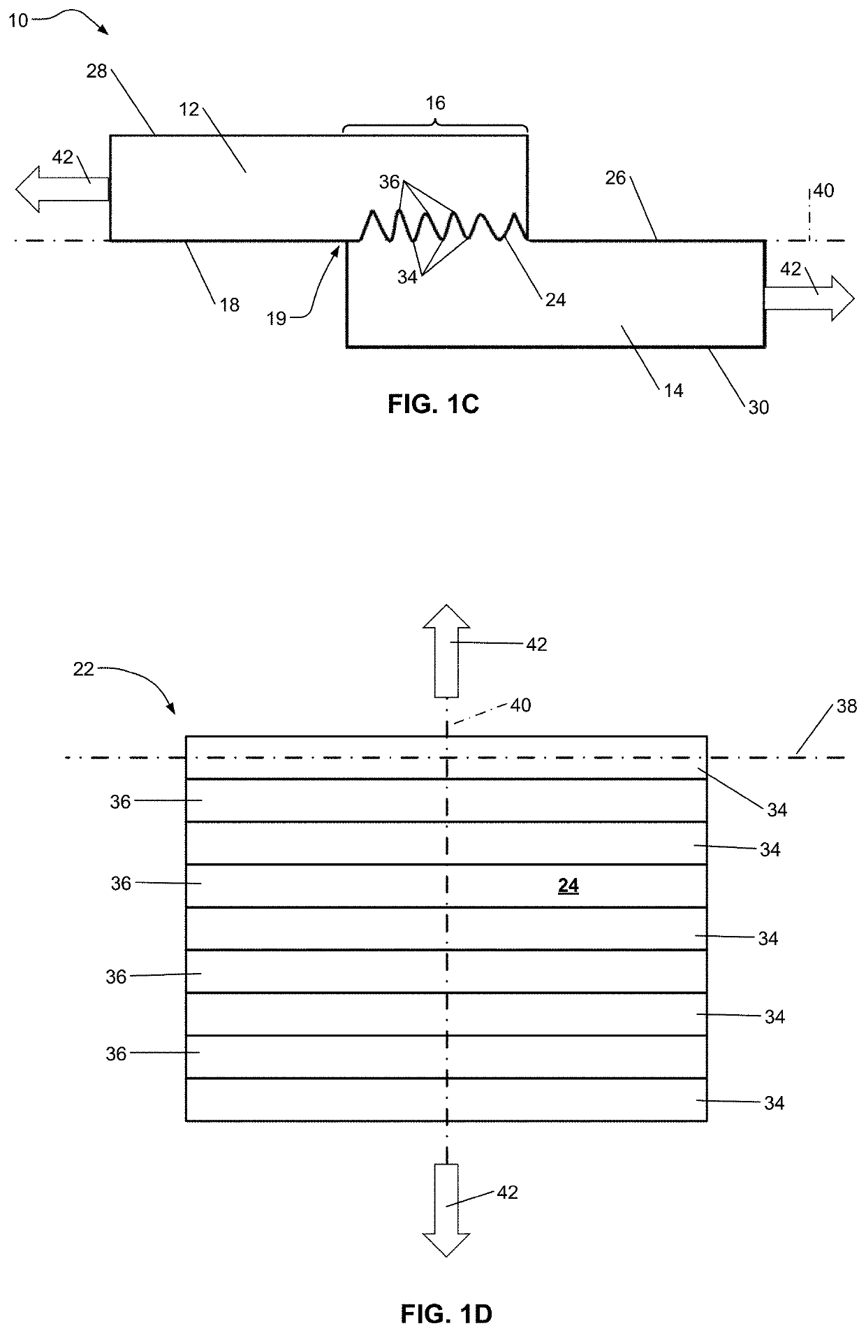
INTRODUCTION[0001]This section provides background information related to the present disclosure which is not necessarily prior art.[0002]The present disclosure pertains to a metal-polymeric composite joint and methods of manufacturing the metal-polymeric composite joint. More specifically, the metal-polymeric composite joint may include a laser-induced micro-anchor structural layer.[0003]Weight reduction for increased fuel economy in vehicles has spurred the use of various lightweight materials, such as aluminum and magnesium alloys as well as use of light-weight reinforced composite materials. While use of such lightweight materials can serve to reduce overall weight and generally improve fuel efficiency, issues can arise in manufacturing certain components. For example, molding large, complex parts from a reinforced composite material may be difficult or infeasible. It may therefore be desirable to join multiple smaller components. However, joining dissimilar materials, such as a...

Claims


Application Information

Patent Timeline
IPC IPC(8): B23K1/005B23K35/30B23K26/364
CPCB23K1/0056B23K35/3053B23K2103/04B23K26/364B23K2103/42B22F3/105B22F7/04B22F7/062B23K26/20B23K26/0624B23K26/324B23K26/3584B23K2103/18
Inventor WANG, HONGLIANGXIAO, XINGCHENGXIAO, GUOXIANFAN, HUA-TZUARINEZ, JORGE F.
Owner GM GLOBAL TECH OPERATIONS LLC
Learn More