Quantum sensor based on rare-earth-ion doped optical crystal and use thereof

a quantum sensor and optical crystal technology, applied in the field of quantum sensors, can solve the problems of extremely prone to disturbance and weak quantum system coheren

Active Publication Date: 2020-03-05
UNIV OF SCI & TECH OF CHINA
View PDF0 Cites 8 Cited by
  • Summary
  • Abstract
  • Description
  • Claims
  • Application Information

AI Technical Summary

Benefits of technology

[0043]In one embodiment, the intensity of the constant magnetic fiel

Problems solved by technology

Generally, the coherence of a quantum system is relatively weak an

Method used


Image

  • Quantum sensor based on rare-earth-ion doped optical crystal and use thereof
  • Quantum sensor based on rare-earth-ion doped optical crystal and use thereof
  • Quantum sensor based on rare-earth-ion doped optical crystal and use thereof

Examples


example 1

Quantum Sensor Based on Rare-Earth-Ion Doped Optical Crystals

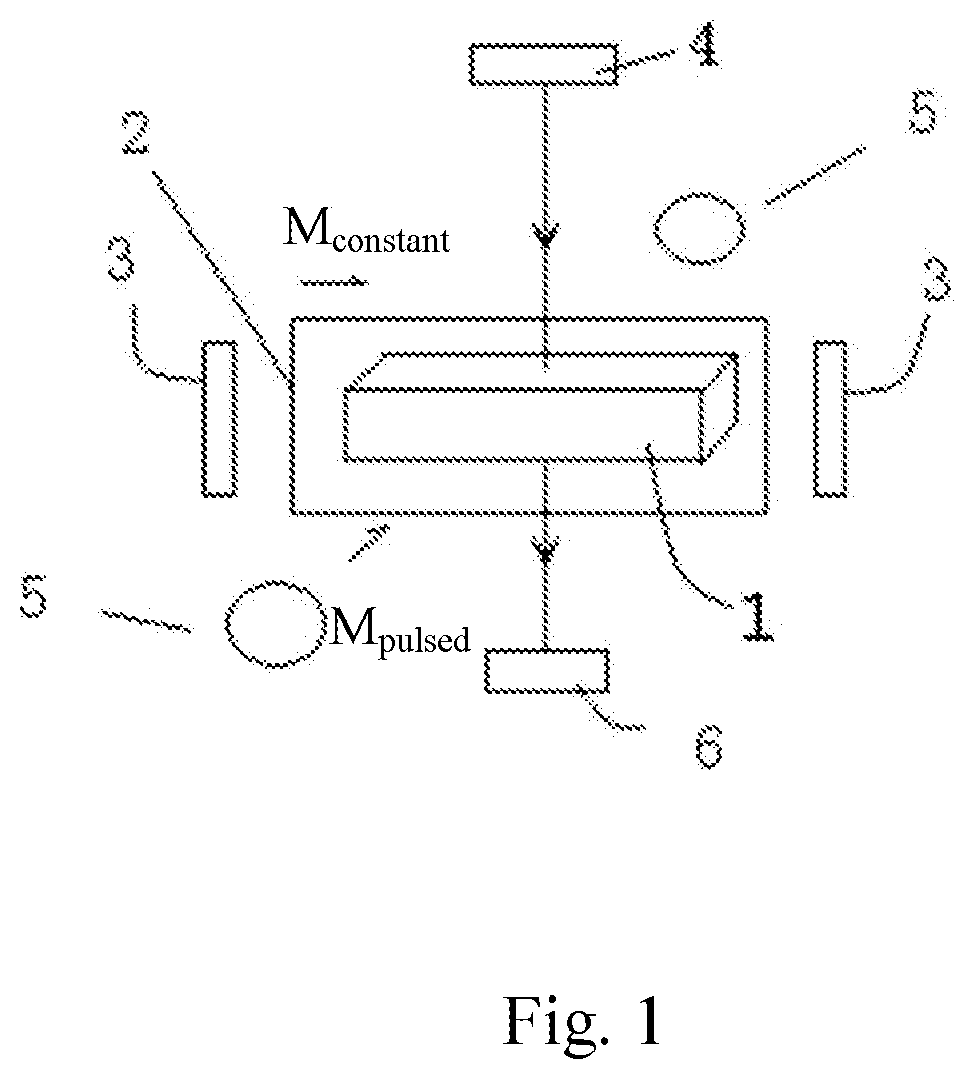
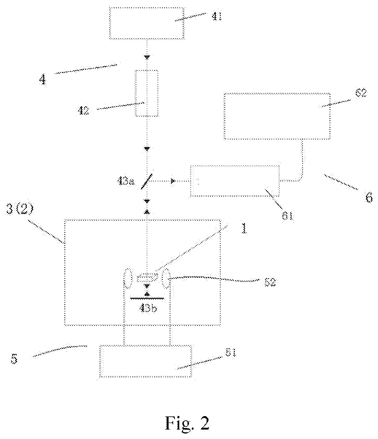
[0113]FIG. 2 is a schematic diagram of an apparatus in an Example of a quantum sensor based on a rare-earth-ion doped optical crystal. As shown in FIG. 2, this apparatus mainly comprises the following parts:[0114]a rare-earth-ion doped optical crystal 1, a low temperature providing unit 2, a constant magnetic field generation unit 3, a light field generation unit 4, a pulsed magnetic field generation unit 5, and a heterodyne Raman scattering light field detection and analysis unit 6.

[0115]Here, the rare-earth-ion doped optical crystal unit 1 is used to achieve detection of an electromagnetic field and generates sensing signals.

[0116]The low temperature providing unit 2 provides a low temperature operating environment to the rare-earth-ion doped optical crystal.

[0117]The constant magnetic field generation unit 3 is used to apply a constant magnetic field. The constant magnetic field generation unit 3 may be integrated to th...

example 2

Measurement of External Disturbing Magnetic Field

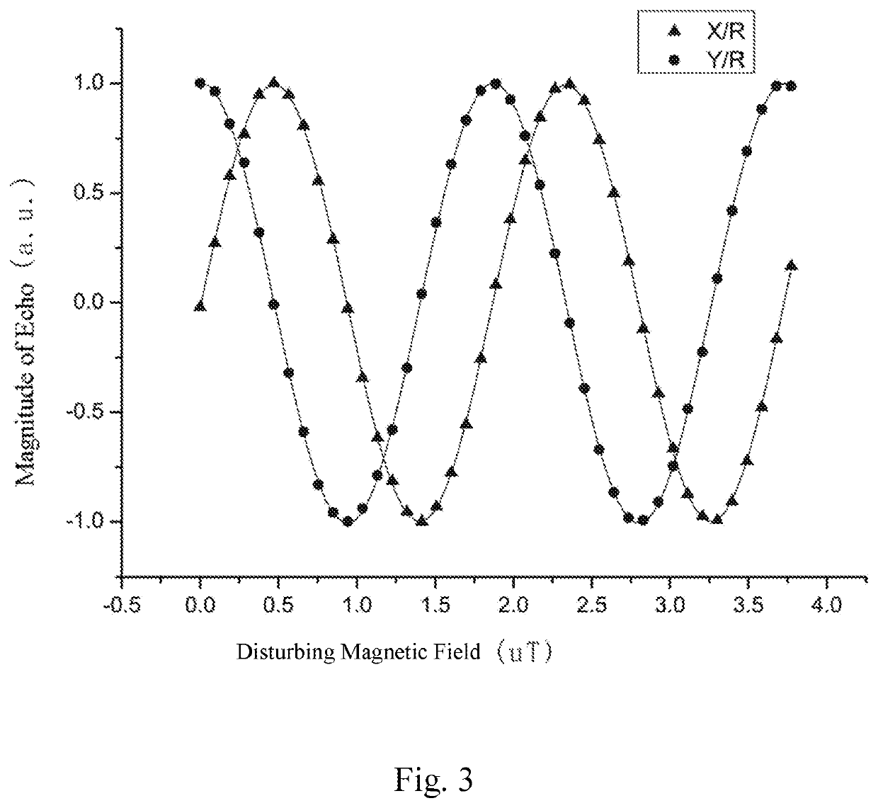
[0137]Magnetic field measurement was performed by using the quantum sensor of Example 1.

[0138]Furthermore, in this Example, the zero first-order Zeeman (ZEFOZ) effect was used to elongate the coherence time of Eu ions by providing a constant magnetic field generated by the constant magnetic field generator 3. At a ZEFOZ point (wherein the magnetic field was about 1.28T, and the orientation of the magnetic field in a crystal D1*D2*b coordinate system was [−0.535, −0.634, 0.558]), the coherence time of spin of the ions was about 30 s. The probe had the longest operation time here, and it was suitable for detection of ultra-low frequency signals. However, the sensitivity of magnetic detection is not high due to poor response to the magnetic field. When the magnetic field was higher than the ZEFOZ point by 200 G, i.e., at 1.30 T, the coherence time was measured to be about 1.5 s by using a spin echo. The magnetic field response was good h...

example 3

Dynamical Decoupling Method

[0144]Further, in addition to a simple spin echo method, a complex dynamical decoupling sequence may be further applied to detect an external alternating magnetic field. A “dynamical decoupling sequence” means that a periodic high-speed flip of spin states of rare-earth-ions is achieved by periodic microwave sequences so as to elongate further the coherence time and the operating time of the probe.

[0145]In this Example, the specific solution was that a pulsed magnetic field generation unit generated a XY-8 dynamical decoupling sequence. The method of performing this sequence was first applying a 90° pulse and applying the following periodic sequence after an interval of 22.248 ms: X-Y-X-Y-Y-X-Y-X, wherein X corresponded to a 180° pulse in a 0° phase and Y corresponded to a 180° pulse in a 90° phase, and the distance between every two 180° pulses was 44.496 ms. The generated echo was finally detected to extract the phase information caused by the disturbing...


PUM


Abstract

Provided is a quantum sensor based on a rare-earth-ion doped optical crystal, having: a rare-earth-ion doped optical crystal; a low temperature providing unit, which provides a low temperature operating environment to the rare-earth-ion doped optical crystal; a constant magnetic field generation unit, which applies a constant magnetic field to the rare-earth-ion doped optical crystal; a light field generation unit, which provides a light field performing optical pumping on the rare-earth-ion doped optical crystal to prepare the rare-earth-ions in an initial spin state, and a light field for exciting Raman scattering of the rare-earth-ion doped optical crystal; a pulsed magnetic field generation unit, which applies a pulsed magnetic field perpendicular to the constant magnetic field to the rare-earth-ion doped optical crystal to make the rare-earth-ion doped optical crystal generate a spin echo; and a heterodyne Raman scattering light field detection and analysis unit, which detects and analyzes a Raman scattering light field radiated from the rare-earth-ion doped optical crystal. Further provided are uses of this quantum sensor for magnetic field sensing and electric field sensing as well as a sensing method.

Description

TECHNICAL FIELD[0001]This disclosure relates to the field of quantum sensors, and particularly to a quantum sensor based on a rare-earth-ion doped optical crystal and use thereof.BACKGROUND ART[0002]Measurement of magnetic fields has a long history of development. Human beings have detected the Earth's magnetic field with a compass to achieve orientation as early as 3rd century BC. In modern society, the magnetic field has wider applications, of which typical examples include maglev trains, magnetic storage, medical magnetic resonance imaging, magnetically confined nuclear fusion apparatuses, and the like. Accordingly, human beings have developed various novel precise magnetic field measurement techniques, of which typical examples include superconductive magnetic flux interferometer sensors, Hall-effect sensors, magnetic resistance sensors, magnetic resonance sensors, and the like. These precise magnetic field measurement techniques have been widely used in various fields such as i...

Claims


Application Information

Patent Timeline
IPC IPC(8): G01R33/12G01R33/032G01N21/65H01S3/16
CPCH01S3/1616G01R33/032H01S3/1608G01R33/07H01S3/1613G01R33/1284G01N21/65H01S3/1611G01R33/26G01R33/323H01S3/102H01S3/0085H01S3/0014H01S3/1086
Inventor ZHOU, ZONGQUANMA, YUTU, TAOLI, CHUANFENGGUO, GUANGCAN
Owner UNIV OF SCI & TECH OF CHINA
Why Eureka
Try Eureka