Nv-center-based microwave-free quantum sensor and uses and characteristics thereof

a quantum sensor and microwave-free technology, applied in the field of microwave-free quantum sensors and uses and characteristics thereof, can solve the problems of diamond radiation damage, inability to remove, and diamonds treated in this way are typically slightly cloudy

Pending Publication Date: 2022-09-29
QUANTUM TECH UG GMBH
View PDF0 Cites 2 Cited by
  • Summary
  • Abstract
  • Description
  • Claims
  • Application Information

AI Technical Summary

Benefits of technology

[0094]In order for the diamonds to later form NV centers, they should have nitrogen atoms, preferably in the form of P1 centers. More simply, the diamonds should preferably be yellow or yellowish. Thus, the diamonds should preferably have a yellow color prior to irradiation, preferably the color “fancy yellow” or “fancy deep yellow” according to the GIA standard of John M. King “Colored Diamonds, colored reference Chart”. Less preferred are diamonds of the GIA classification or “ fancy light yellow”, as they contain less nitrogen and accordingly result in diamonds with a lower density of NV centers. The stronger the yellowish color the more densely the NV centers are concentrated in the diamonds later. Less preferably, the diamond blank or blanks comprise nitrogen atoms together with hydrogen, as the latter has a compensating effect. However, such diamonds can be used in a pinch. N-doping with sulfur can also lead to an increase in the yield of NV centers.
[0395]A housing, as proposed here, and the sensor built on top of it enables, at least in some realizations, the compact design and the combination of conventional circuit technology with quantum sensor technology. However, the advantages are not limited to this.

Problems solved by technology

Irradiation with the electron beam or neutron beam causes radiation damage in the diamond, which cannot be removed even with subsequent annealing.
Therefore, diamonds treated in this way are typically slightly cloudy.
The intermediate annealing already improves the healing of the radiation damage, but cannot prevent the damage from agglomerating and the diamond from becoming cloudy.
Irradiation with the electron beam causes radiation damage to the diamond, which cannot be removed even with subsequent annealing.
Therefore, diamonds treated in this way are typically slightly cloudy.
The irradiation with the electron beam causes radiation damage in the diamond, which cannot be removed even with subsequent annealing.
Therefore, diamonds treated in this way are typically slightly cloudy.
This procedure has the massive disadvantage that flaws form in the diamond crystal during the high-energy irradiation.
However, this can only be done with partial success.
These clusters of flaws lead to a clouding of the jewelry diamonds and thus to a deficiency with regard to the so-called “clarity” of the jewelry diamonds.
From the paper M. Capelli, A. H. Heffernan, T. Ohshima, H. Abe, J. Jeske, A. Hope, A. D. Greentree, P. Reineck, B. C. Gibson, Increased nitrogen-vacancy center creation yield in diamond through electron beam irradiation at high temperature, Carbon (2018), doi: https: / / doi.org / 10.1016 / j.carbon.2018.11.051, an increase in NV center yield is known but not yet sufficient.
Therefore, the technical teaching US 2015 0 090 033 A1 only discloses a method for producing NV centers with a typical NV center density of 10 ppm and unfortunately does not disclose a method for producing NV centers with a typical NV center density of more than 10 ppm.
There is a significant lack of relevant literature.
None of the above fonts allow the use of a microwave-free and radio-wave-free sensor system that does not require alignment of the diamond crystal.
Such HPHT diamonds contain little hydrogen, which from experience is typically not helpful for the formation of NV centers.
However, CVD diamonds have a larger amount of hydrogen, which hinders the formation of the NV centers.
In this respect, this variant is also claimed here, although it is not optimal.
Otherwise, radiation exposure of the surrounding tissue by the microwave radiation occurs, which massively limits the use of sensors with microwave excitation of the excited paramagnetic centers to an intermediate level for such purposes.
The performance of a quantum mechanical sensor system can be massively limited by an unfavourable housing.
In particular, for example, a housing with ferromagnetic subcomponents can cause distortions or shielding of magnetic fields and thus limit the usefulness of the sensor system.
Also, an unfavorable housing can decisively increase the production costs of such a sensor device.
According to the disclosure, it was thus realized that the fundamental problem of radio astronomy to detect a very small signal in front of a thermally noisy noise background is the same problem that occurs in quantum sensors.
However, compensation with a differently constructed compensating radiation source (PLK) is explicitly less preferred also possible.
This can also have cost reasons.

Method used


Image

  • Nv-center-based microwave-free quantum sensor and uses and characteristics thereof
  • Nv-center-based microwave-free quantum sensor and uses and characteristics thereof
  • Nv-center-based microwave-free quantum sensor and uses and characteristics thereof

Examples


Embodiment Construction

[0477]The figures show selected examples in a schematic and simplified manner. They serve the purpose of clarification. The features of the description and the figures can be combined with each other as far as reasonable. The stress results from the respective valid set of claims.

FIG. 1

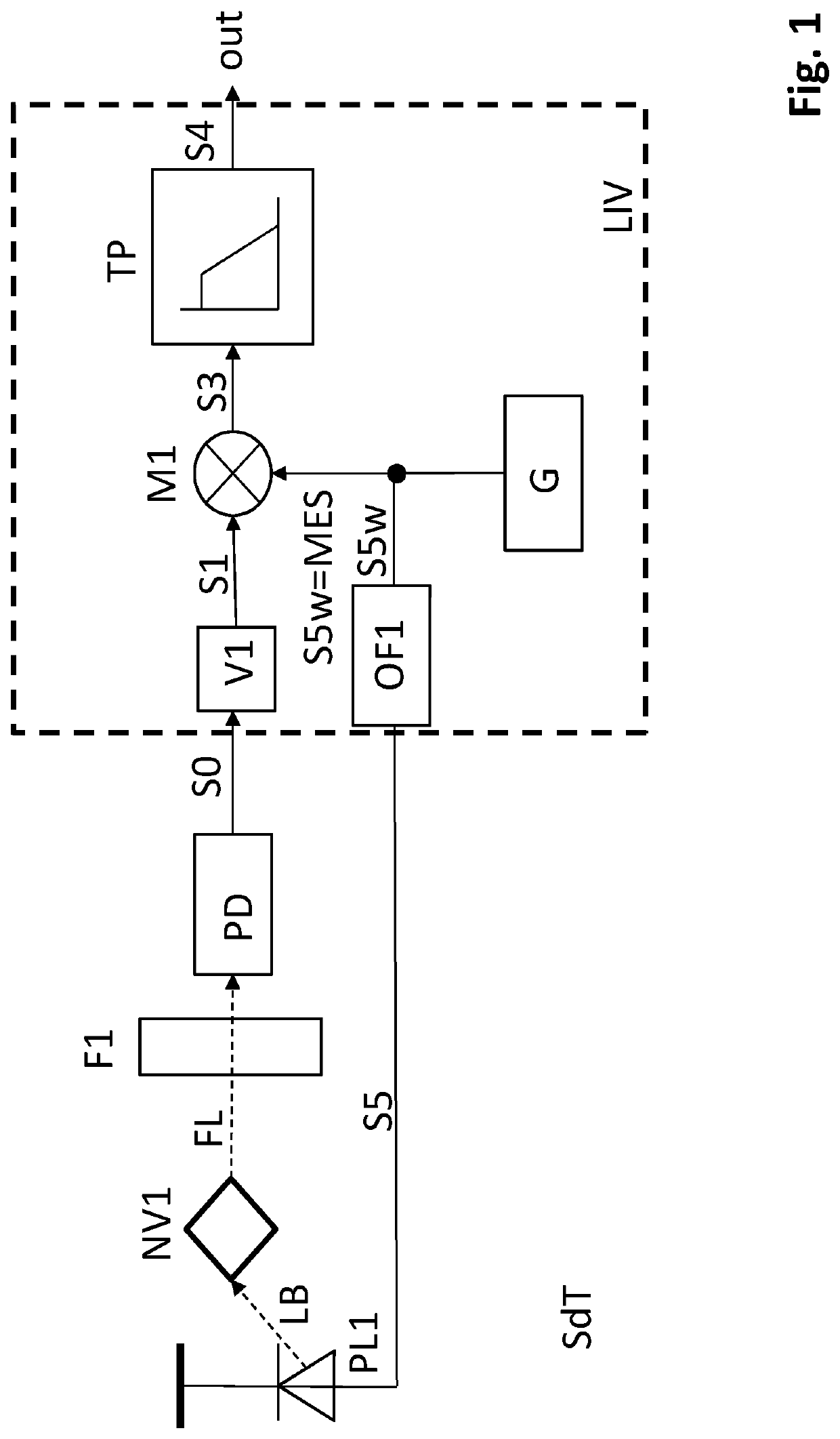
[0478]FIG. 1 shows a schematically simplified evaluation circuit according to the state of the art (SdT). A pump radiation source (PL1) irradiates the diamond sensor element with the NV center as paramagnetic center (NV1) with pump radiation (LB). This pump radiation (LB) causes the paramagnetic center (NV1) to emit fluorescence radiation (FL). The intensity (Ipmp) of the pump radiation (LB) from the pump radiation source (PL1) is modulated. This modulation of the intensity (Ipmp) of the pump radiation (LB) of the pump radiation source (PL1) depends on a transmission signal (S5). Preferably, the intensity (Ipmp) of the pump radiation (LB) of the pump radiation source (PL1) is substantially proportiona...


PUM

PropertyMeasurementUnit
energyaaaaaaaaaa
temperatureaaaaaaaaaa

Abstract

A sensor system is based on diamonds with a high density of NV centers. The description includes a) methods for producing the necessary diamonds of high NV center density, b) characteristics of such diamonds, c) sensing elements for utilizing the fluorescence radiation of such diamonds, d) sensing elements for utilizing the photocurrent of such diamonds, e) systems for evaluating these quantities, f) reduced noise systems for evaluating these systems, g) enclosures for using such systems in automatic placement equipment, g) methods for testing these systems, and h) a musical instrument as an example of an ultimate application of all these devices and methods.

Description

CROSS REFERENCE TO RELATED APPLICATIONS[0001]The present patent application is a national stage of, and claims priority to, Patent Cooperation Treaty Application No. PCT / DE2020 / 100648, filed on Jul. 22, 2020, which application claims the priority of the German patent applications DE 10 2019 009 153.1 filed on Jul. 25, 2019, DE 10 2019 009 155.8 filed on Aug. 5, 2019, DE 10 2019 005 484.9 filed on Aug. 5, 2019, DE 10 2019 129 092.9 filed on Oct. 28, 2019, DE 10 2019 130 115.7 filed on Nov. 7, 2019, DE 10 2020 107 831.5 filed on Mar. 22, 2020, and DE 10 2020 003 532.9 filed on Apr. 5, 2020, the disclosures of which are incorporated by reference in the present patent application.TECHNICAL FIELD[0002]The disclosure relates, inter alia, to a method and a device for generating acoustically equivalent electrical and digital signals by means of sensors based on quantum mechanical effects as microphones or pickups for musical instruments and other technical and medical instruments. The prese...

Claims


Application Information

Patent Timeline
Patent Type & Authority Applications(United States)
IPC IPC(8): G01N24/00C01B32/26C01B32/28C09K11/65
CPCG01N24/006C01B32/26C01B32/28C09K11/65C01P2002/52C01P2006/60C01P2006/88G01R33/032G01R33/26
Inventor MEIJER, JAN BERENDSTAACKE, ROBERTMEIJER, NILSBURCHARD, BERND
Owner QUANTUM TECH UG GMBH
Why Eureka
Try Eureka