This helps you quickly interpret patents by identifying the three key elements:
Problems solved by technology
Method used
Benefits of technology
Benefits of technology
The present patent provides a power unit structure for vehicles that prevents the power unit room from being too tall and wide. This structure also allows for the addition of a water heating heater without increasing the size of the power unit room.
Problems solved by technology
Incidentally, when the front side member is crushed and deformed due to the collision load from the front side of the vehicle, it is conceivable that the front side member is not easily crushed and deformed at the mounting place of the mounting part in the front side member.
Method used
Image
Click on the blue label to locate the original text in one second.
Reading with bidirectional positioning of images and text.
Examples
first embodiment
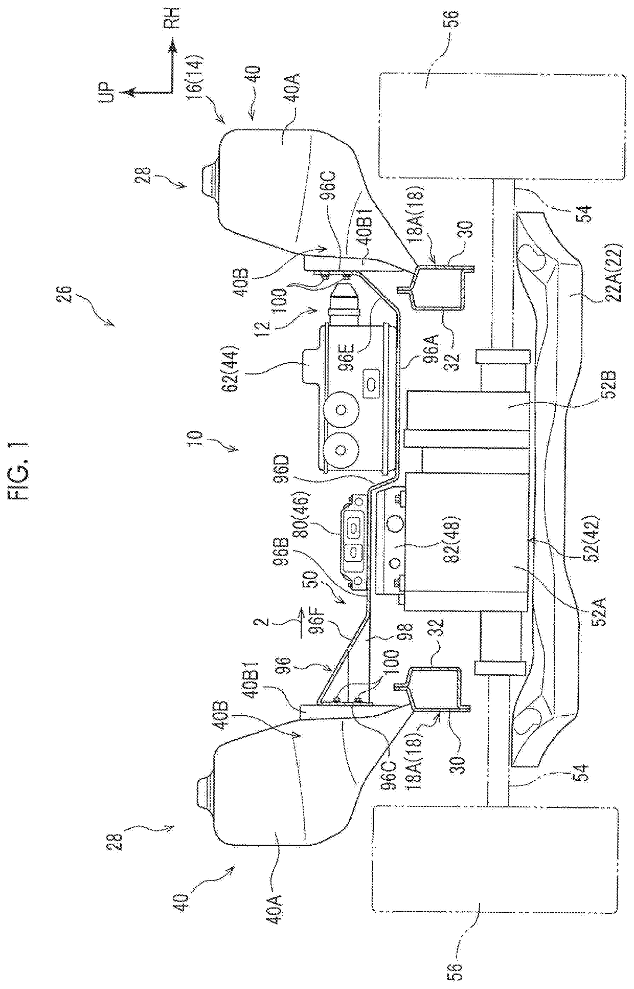
[0058]Hereinafter, a first embodiment of a power unit structure for a vehicle will be described using FIGS. 1 to 7. An arrow FR appropriately shown in each drawing indicates the front side of the vehicle, an arrow UP indicates the upper side of the vehicle, and an arrow RH indicates the right side in a vehicle width direction of the vehicle.
[0059]First, the configuration of a vehicle body front portion 16 configuring a portion on the front side of the vehicle of a vehicle body 14 having a “power unit room 12” in which a power unit 10 to which the power unit structure for a vehicle according to this embodiment is applied is disposed will be described using FIG. 7.
[0060]The vehicle body front portion 16 includes a pair of “front side members 18”, a bumper reinforcement 20 (hereinafter referred to as a “bumper R / F 20”), a suspension member 22, and a dash panel 24, as vehicle body constituent members.
[0061]The front side member 18 configures a part of a “side portion 28 in the vehicle w...
second embodiment
[0109]Hereinafter, a second embodiment of the power unit structure for a vehicle will be described using FIGS. 8 and 9. The same constituent portions as those of the first embodiment described above are denoted by the same reference numerals, and description thereof is omitted.
[0110]A power unit 110 according to this embodiment basically has the same configuration as the power unit 10 according to the first embodiment. However, the power unit 110 is characterized in that a “mounting part 112” that supports the electric power distribution unit 44 and the water heating heater 46 is mounted to the front side members 18.
[0111]Specifically, the mounting part 112 includes a main body portion 114 and reinforcing plate portions 116, 118. The main body portion 114 basically has the same configuration as the main body portion 96 and is configured to include a placing portion 114A on which the electric power distribution unit 44 is placed, a placing portion 114B on which the water heating heat...
third embodiment
[0128]Hereinafter, a third embodiment of the power unit structure for a vehicle will be described using FIG. 10. The same constituent portions as those of the first embodiment described above are denoted by the same reference numerals, and description thereof is omitted.
[0129]A power unit 140 according to this embodiment basically has the same configuration as the power unit 10 according to the first embodiment. However, there is a first feature in that the power unit 140 is not provided with the water heating heater 46 according to the specifications of the vehicle 26. Further, there is a second feature in that the electric power distribution unit 44 is mounted in a cantilevered state to the front side member 18 on the right side in the vehicle width direction of the vehicle by a “mounting part 142”.
[0130]Specifically, the mounting part 142 includes a main body portion 144 and a reinforcing plate portion 146. The main body portion 144 includes a placing portion 144A having the same...
PUM
Abstract
A power unit structure for a vehicle includes a motor disposed in a power unit room of the vehicle and configured to transmit a driving force to drive wheels of the vehicle, an electric power converter disposed in the power unit room of the vehicle, and an electric powerdistributor disposed in the power unit room of the vehicle. The electric power converter is configured to convert supplied electric power into electric power to be supplied to the motor and is disposed on an upper side of the motor. The electric power distributor is configured to distribute electric power supplied from a power supply to the electric power converter and is disposed at a position where at least a part of the electric power distributor overlaps the electric power converter in an up-down direction of the vehicle when viewed from a vehicle front-rear direction or a vehicle width direction.
Description
CROSS-REFERENCE TO RELATED APPLICATIONS[0001]This application claims priority to Japanese Patent Application No. 2018-159625 filed on Aug. 28, 2018, which is incorporated herein by reference in its entirety including the specification, drawings and abstract.BACKGROUND1. Technical Field[0002]The present disclosure relates to a power unit structure for a vehicle.2. Description of Related Art[0003]Japanese Unexamined Patent Application Publication No. 2011-020628 (JP 2011-020628 A) discloses a motor room structure. In this motor room structure, an inverter (an electric power conversion unit) for converting electric power from a power supply and supplying it to a motor is disposed on the upper side of the motor in an up-down direction of the vehicle.[0004]On the other hand, in a strong electricity box structure of an electric vehicle described in Japanese Unexamined Patent Application Publication No. 09-277840 (JP 09-277840 A), a junction box (an electric power distribution unit) is dis...
Claims
Application Information
Patent Timeline
Application Date:The date an application was filed.
Publication Date:The date a patent or application was officially published.
First Publication Date:The earliest publication date of a patent with the same application number.
Issue Date:Publication date of the patent grant document.
PCT Entry Date:The Entry date of PCT National Phase.
Estimated Expiry Date:The statutory expiry date of a patent right according to the Patent Law, and it is the longest term of protection that the patent right can achieve without the termination of the patent right due to other reasons(Term extension factor has been taken into account ).
Invalid Date:Actual expiry date is based on effective date or publication date of legal transaction data of invalid patent.

