Electric machine cooling features

a technology of electric machines and cooling features, which is applied in the direction of manufacturing stator/rotor bodies, magnetic circuit shapes/forms/construction, windings, etc., can solve the problems of reducing the efficiency of heat transfer into aluminum, limiting the contact resistance between aluminum and the electric machine, and generating heat, so as to reduce the contact resistance of the interface

Active Publication Date: 2020-03-12
HAMILTON SUNDSTRAND CORP
View PDF5 Cites 2 Cited by
  • Summary
  • Abstract
  • Description
  • Claims
  • Application Information

AI Technical Summary

Benefits of technology

[0005]Disclosed is a stator comprising: a first member having a first plurality of axially opposing ends including a first front end and a first back end mutually spaced along a first stator center axis, a first outer diameter (OD) side and a first inner diameter (ID) side, wherein first member comprises laminated steel; a plurality of cooling features disposed directly against the first member, wherein the plurality of fins spans between the first plurality of axially opposing ends of the first member, and wherein: the stator comprises a base layer disposed directly against the first member, between the first member and the cooling features, thereby reducing an interface contact resistance between the first member and the plurality of cooling features.

Problems solved by technology

An electric machine generates heat due to many causes including electromagnetic losses both in copper windings and in laminated steel cores.
However, the limiting factor of this design is the contact resistance between the aluminum of and the steel of the stator.
Further, asperities on the surface of the stator preclude the shrink fit from creating an interface with intimate contact lowering the efficacy by which heat can transfer into the aluminum.

Method used


Image

  • Electric machine cooling features
  • Electric machine cooling features
  • Electric machine cooling features

Examples


Embodiment Construction

[0027]A detailed description of one or more embodiments of the disclosed apparatus and method are presented herein by way of exemplification and not limitation with reference to the Figures.

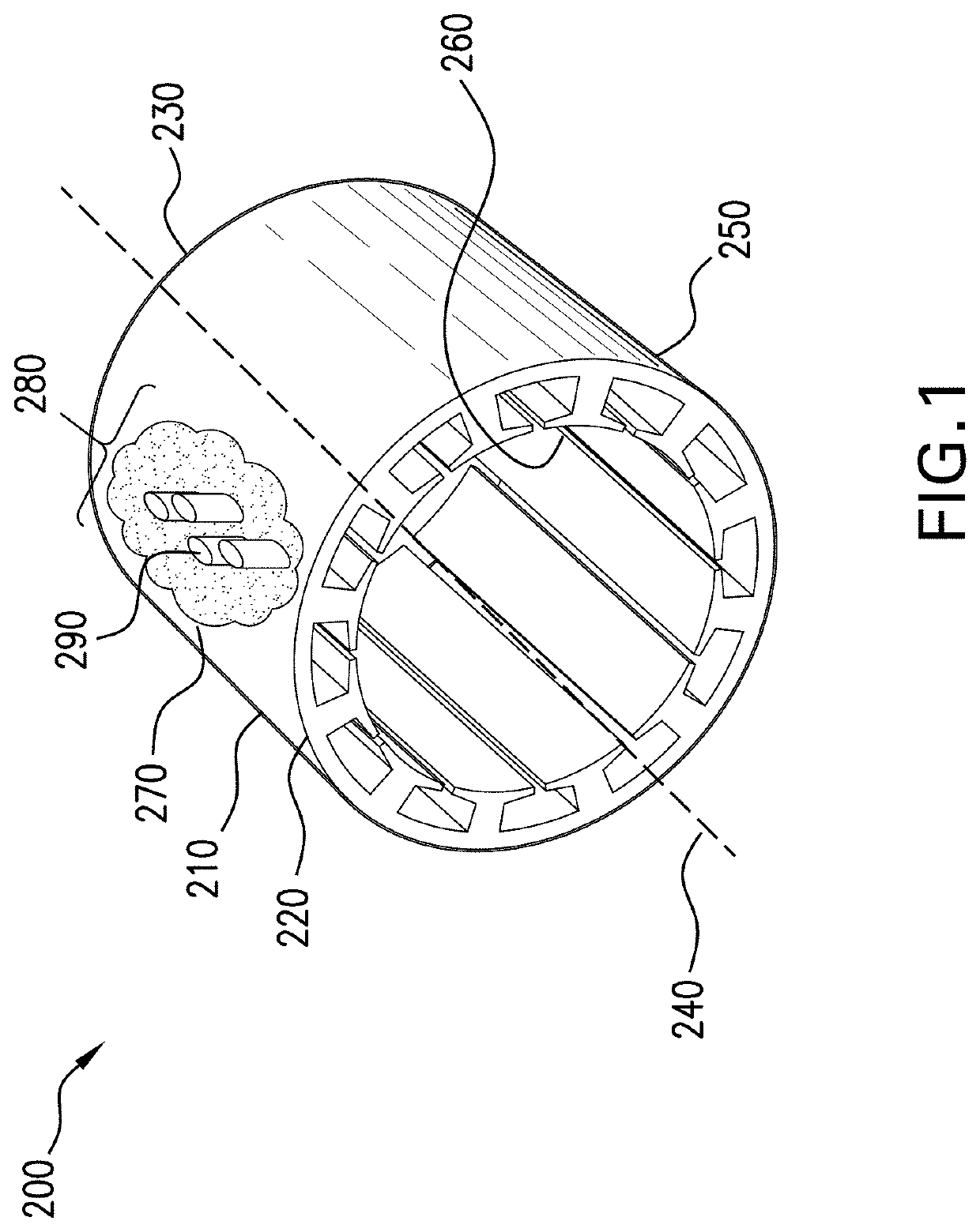
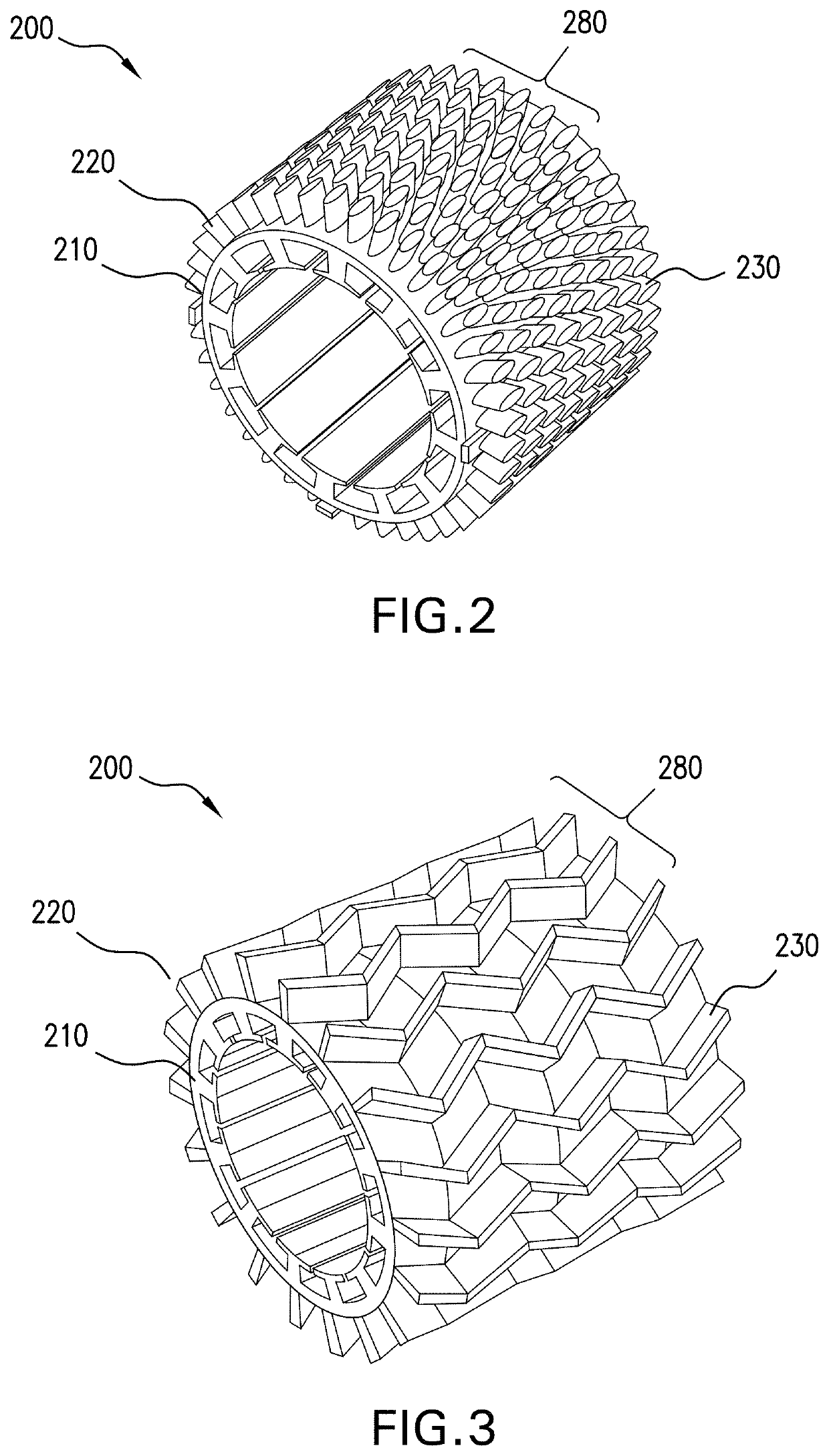
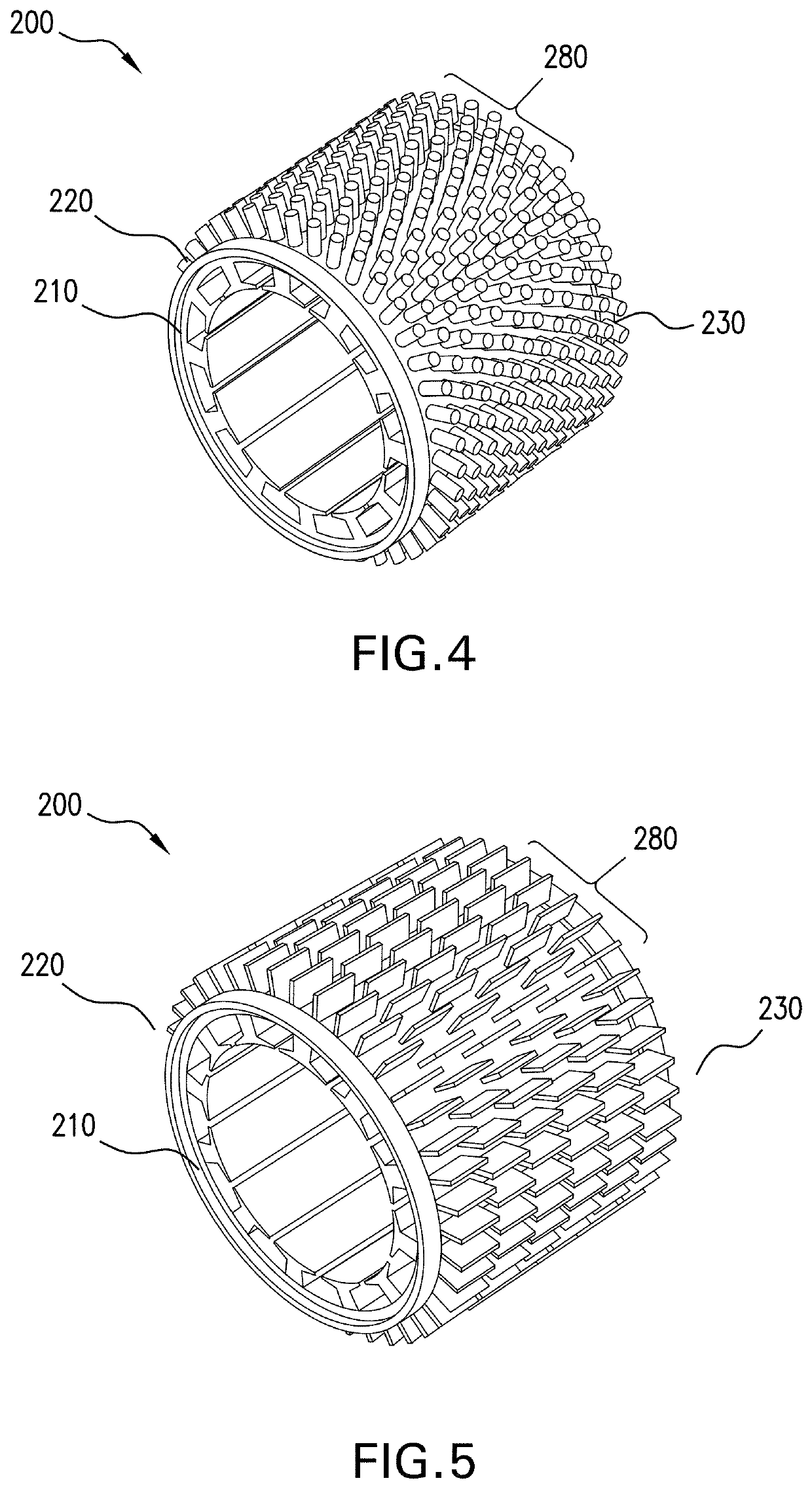
[0028]Turning to FIG. 1, disclosed is a stator 200 comprising a first cylindrical member 210 that may have a first plurality of axially opposing ends including a first front end 220 and a first back end 230 mutually spaced along a first stator center axis 240. The first member 210 may have a first outer diameter (OD) side 250 and a first inner diameter (ID) side 260. In addition, the first member 210 can be formed of material such as laminated electrical steel.

[0029]In one embodiment, a base layer 270, a portion of which is illustrated schematically in FIG. 1, may be disposed directly against the first OD side 250 of the first member 210. This base layer 270 can be formed of material that is different than the material forming the first member 210. In one embodiment, the base layer 270 is formed ...


PUM


Abstract

Disclosed is a stator having: a first member having a first plurality of axially opposing ends including a first front end and a first back end mutually spaced along a first stator center axis, a first outer diameter (OD) side and a first inner diameter (ID) side, wherein first member comprises laminated steel; a plurality of cooling features disposed directly against the first member, wherein the plurality of fins spans between the first plurality of axially opposing ends of the first member, and wherein: the stator comprises a base layer disposed directly against the first member, between the first member and the cooling features, thereby reducing an interface contact resistance between the first member and the plurality of cooling features.

Description

BACKGROUND[0001]Exemplary embodiments pertain to the art of motor components and more specifically to motor cooling features mounted to a motor to provide reduced thermal resistance between the cooling features and the motor.[0002]An electric machine generates heat due to many causes including electromagnetic losses both in copper windings and in laminated steel cores. One approach to dissipate such heat is to provide a metal sleeve that is place around the stator. Natural or forced convection can then carry the heat away.[0003]One way to improve convection is to provide a sleeve that includes pins or plate fins. Such a sleeve is typically formed by machining aluminum such that it includes the pins or plate fins. The sleeve is then slid over the outer diameter of the stator. The sleeve can then be shrink fit to form a tight connection to the stator.[0004]However, the limiting factor of this design is the contact resistance between the aluminum of and the steel of the stator. Further...

Claims


Application Information

Patent Timeline
Patent Type & Authority Applications(United States)
IPC IPC(8): H02K9/22H02K1/12H02K3/02H02K3/46H02K15/02
CPCH02K3/02H02K15/02H02K9/22H02K3/46H02K1/12H02K5/18H02K15/14H02K9/227
Inventor TANGUDU, JAGADEESH KUMARYUN, THOMAS M.SHARON, JOHN A.
Owner HAMILTON SUNDSTRAND CORP
Why Eureka
Try Eureka