Cutter blade and lawn mower

Active Publication Date: 2020-04-02
HONDA MOTOR CO LTD
View PDF0 Cites 10 Cited by
  • Summary
  • Abstract
  • Description
  • Claims
  • Application Information

AI Technical Summary

Benefits of technology

[0027]In the cutter blade and the lawn mower of the present invention, it becomes pos

Problems solved by technology

However, when outer ends of the blade are displaced upward or downward by the centrifugal force generated during rotation of the cutter blade, the lawn mowing perfo

Method used


Image

  • Cutter blade and lawn mower
  • Cutter blade and lawn mower
  • Cutter blade and lawn mower

Examples


Embodiment Construction

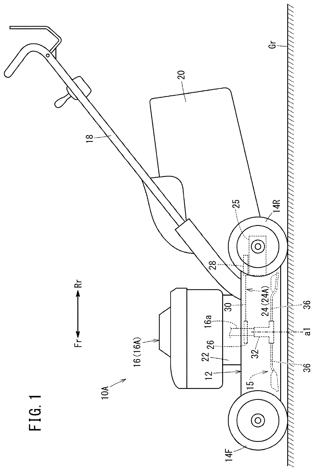
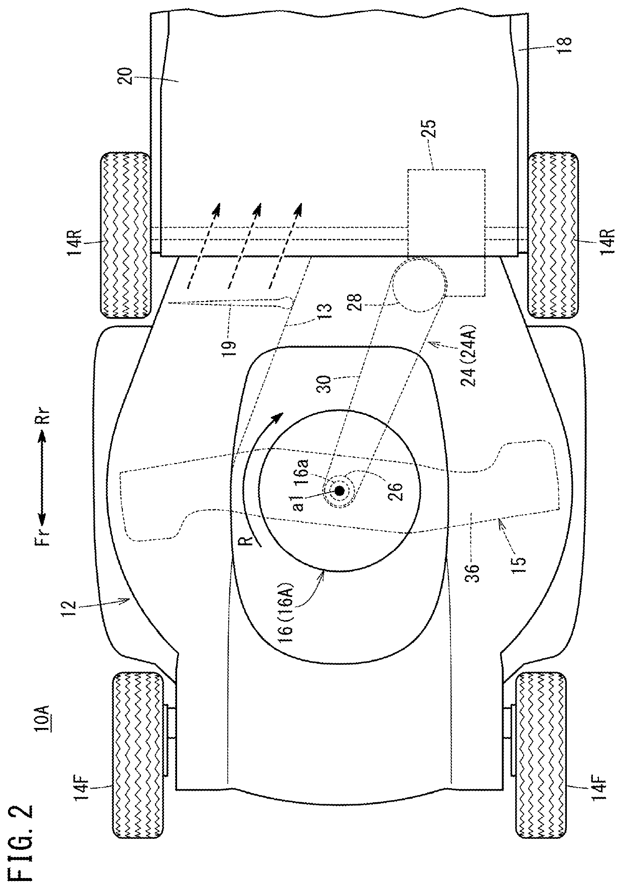
[0038]A lawn mower 10A shown in FIGS. 1 and 2 is a walk-behind, self-propelled working machine for cutting lawn grass. In FIGS. 1 and 2, an arrow Fr denotes the front side (same as the front side as viewed from an operator) of the lawn mower 10A, and an arrow Rr denotes the rear side (same as the rear side as viewed from the operator) of the lawn mower 10A. (Also in FIG. 7 showing a lawn mower 10B having another structure, the arrow Fr denotes the front side of the lawn mower 10B, and the arrow Rr denotes the rear side of the lawn mower 10B).

[0039]The lawn mower 10A includes a housing 12 as a machine body, left and right front wheels 14F provided on the front side of the housing 12, left and right rear wheels 14R provided on the rear side of the housing 12, a cutter blade 15 accommodated inside the housing 12 for cutting lawn grass, a prime mover 16 provided above the housing 12, and a control handle 18 extending backward from the housing 12.

[0040]As shown in FIG. 2, in a plan view,...


PUM


Abstract

A cutter blade for a lawn mower is provided with an upper blade and a lower blade. The upper blade has an upper blade base and an upper outer end positioned above and further radially outward than the upper blade base. The lower blade has a lower blade base and a mowing section positioned below and further radially outward than the lower blade base. The upper blade base overlaps the lower blade base.

Description

TECHNICAL FIELD[0001]The present invention relates to a cutter blade and a lawn mower.BACKGROUND ART[0002]Rotary lawn mowers cut lawn grass by rotating a cutter blade along lawn grass. In the lawn mowers, it is known that some rotary lawn mowers include a cutter blade having double blades, i.e., an upper blade and a lower blade (e.g. see the specification of U.S. Patent Application Publication No. 2006 / 0042216).SUMMARY OF INVENTION[0003]Some conventional cutter blades for the lawn mower have structure where ribs, etc. are provided for improvement of rigidity, in order to suppress displacement amount of the blade by the centrifugal force during rotation. However, when outer ends of the blade are displaced upward or downward by the centrifugal force generated during rotation of the cutter blade, the lawn mowing performance (finishing appearance) may be degraded undesirably, and when stress is generated as a result of displacement, the blade strength may be decreased undesirably.[0004]...

Claims


Application Information

Patent Timeline
IPC IPC(8): A01D34/73
CPCA01D34/73A01D34/63
Inventor KURIHARA, MAIMINAMI, FUMIONISHI, YUKOKOBAYASHI, HIROSHI
Owner HONDA MOTOR CO LTD
Why Eureka
Try Eureka