Substrate retaining apparatus, system including the apparatus, and method of using same

a technology for retaining apparatus and substrates, applied in the direction of coatings, chemical vapor deposition coatings, metallic material coating processes, etc., can solve the problems of increasing the time and expense of devices formed using such methods, unwanted process variation in subsequent processing, and affecting the effect of cooling

Pending Publication Date: 2020-04-02
ASM IP HLDG BV
View PDF16 Cites 213 Cited by
  • Summary
  • Abstract
  • Description
  • Claims
  • Application Information

AI Technical Summary

Benefits of technology

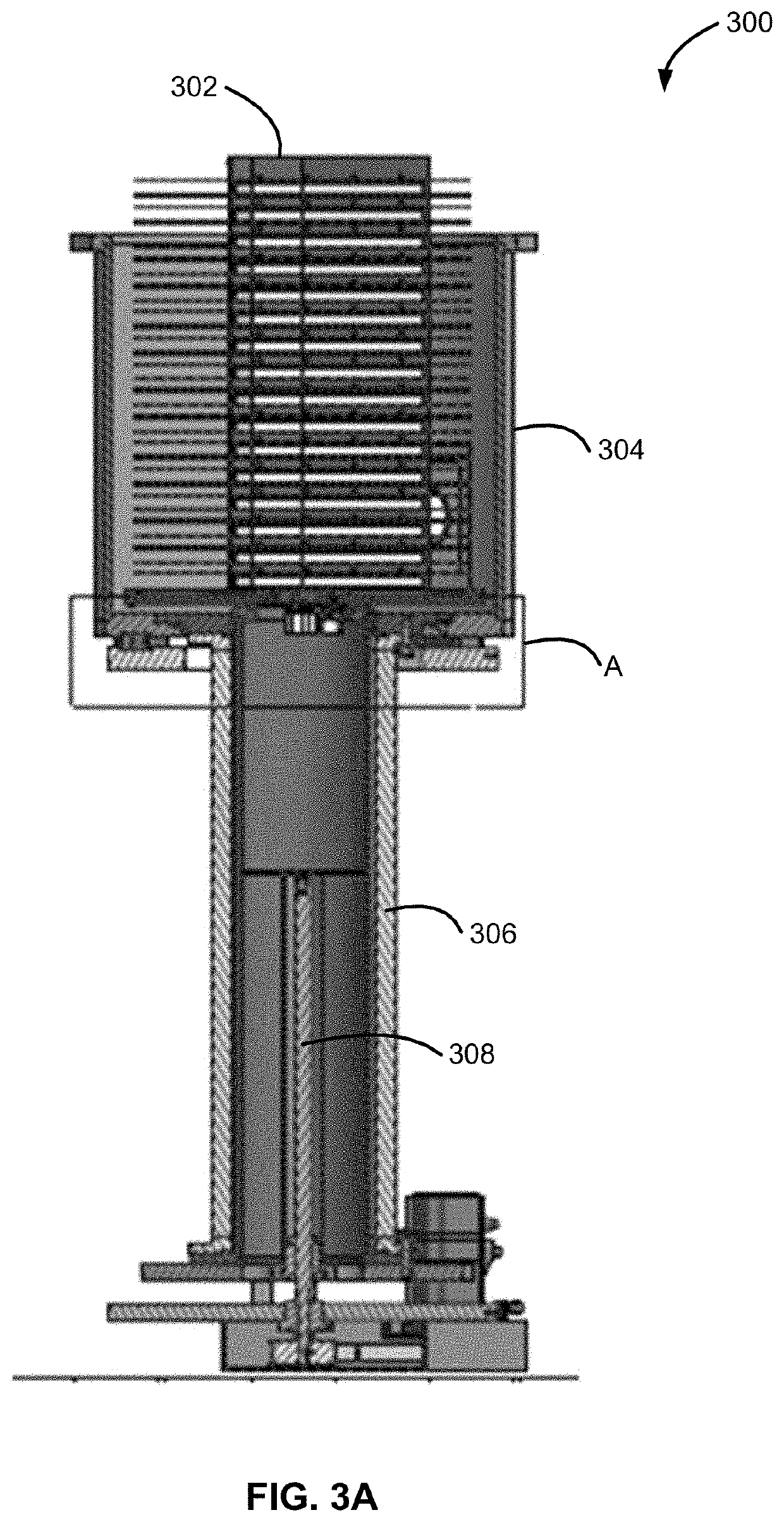
[0006]Various embodiments of the present disclosure relate to apparatus for retaining substrates—e.g., within a load lock of a reactor system. While the ways in which various embodiments of the present disclosure address drawbacks of prior substrate retention apparatuses and load locks are discussed in more detail below, in general, various embodiments of the disclosure provide a substrate retaining apparatus that can rapidly cool substrates to desired temperatures, mitigate thermal crosstalk between substrates, mitigate undesired surface oxidation of a surface of a substrate, mitigate variation of temperatures across the surface of the substrate, and / or reduce contamination on the substrate surface.

Problems solved by technology

Any variation in the oxidation of the surface can cause unwanted process variation in subsequent processing, such as a pre-clean process for the removal of native oxides, carbon and / or other materials for, for example, integrated pre-epi and / or other surface preparation.
Additionally, it can take a relatively long time for substrates to cool to a desired temperature before the substrates are transferred from the load lock—e.g., to another reaction chamber or to the ambient environment.
The relatively long cooling time can add unwanted time and expense to devices formed using such methods.
Further, a relatively hot substrate may undesirably heat a relatively cool substrate.
Outgassing of relatively hot substrates can also pose a problem within a load lock.

Method used


Image

  • Substrate retaining apparatus, system including the apparatus, and method of using same
  • Substrate retaining apparatus, system including the apparatus, and method of using same
  • Substrate retaining apparatus, system including the apparatus, and method of using same

Examples


Embodiment Construction

[0024]The description of exemplary embodiments provided below is merely exemplary and is intended for purposes of illustration only; the following description is not intended to limit the scope of the disclosure or the claims. Moreover, recitation of multiple embodiments having stated features is not intended to exclude other embodiments having additional features or other embodiments incorporating different combinations of the stated features.

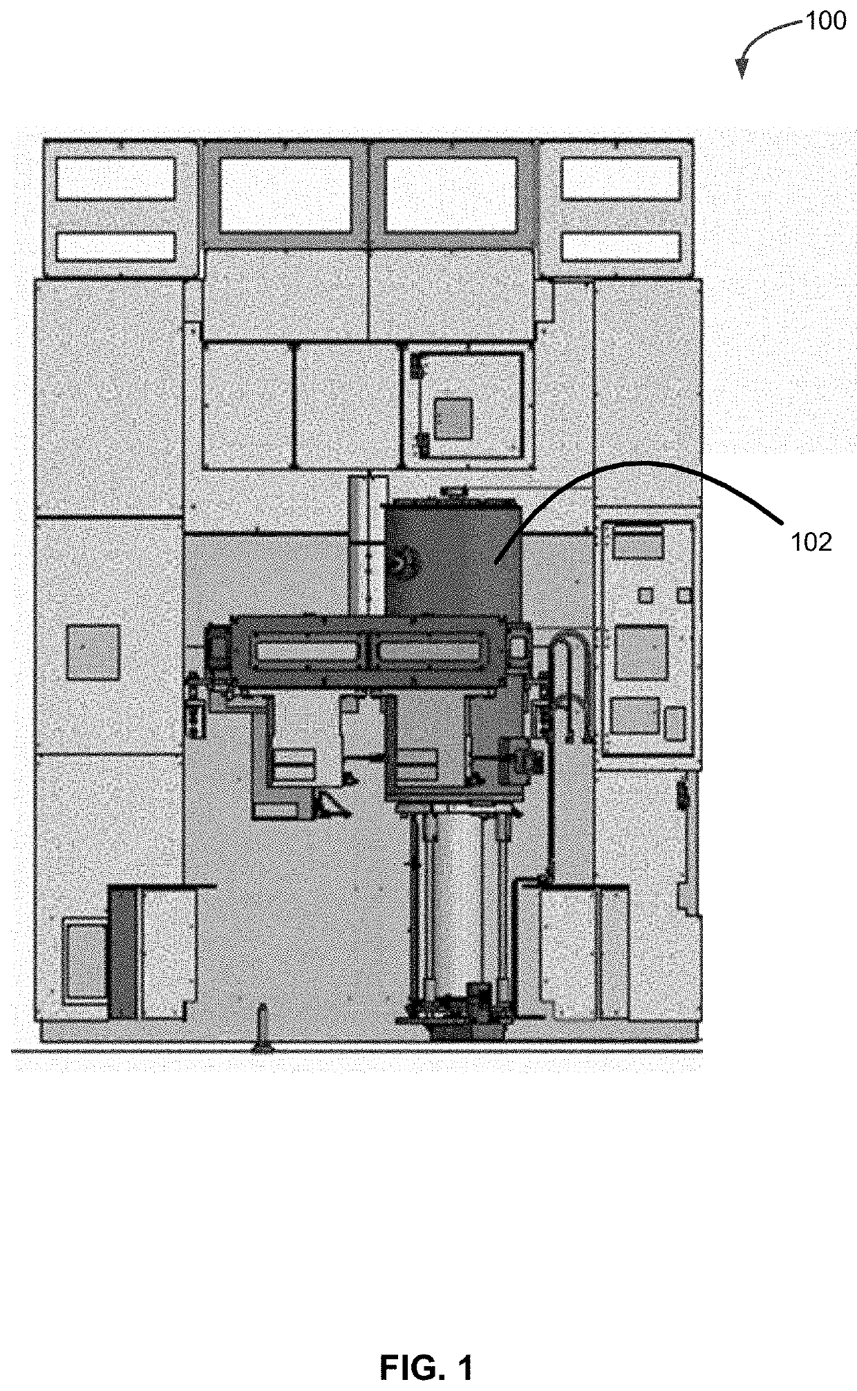
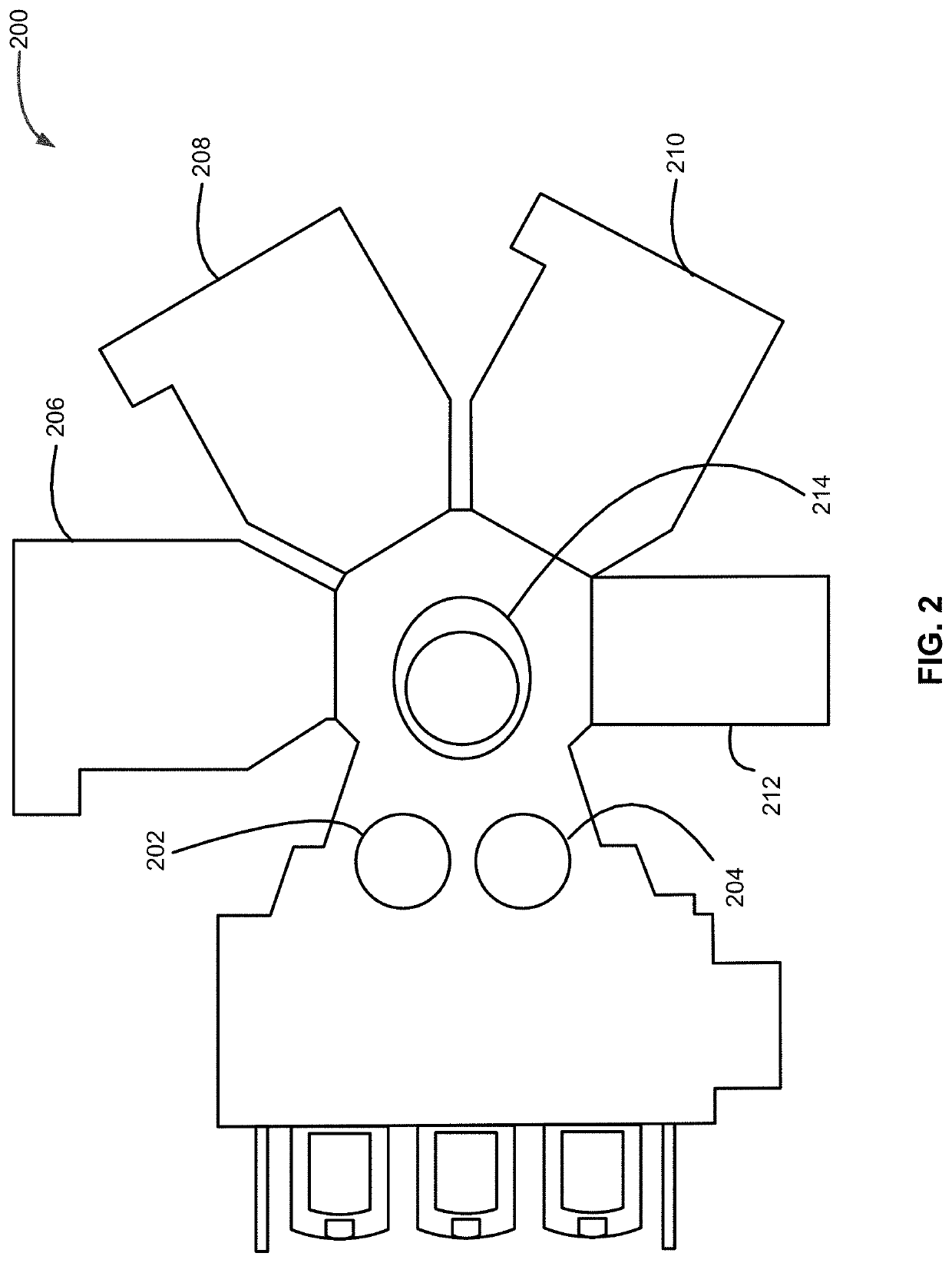
[0025]The present disclosure generally relates to substrate retaining apparatus, load lock assemblies including the substrate retaining apparatus, and reactor systems including the substrate retaining apparatus and / or load lock assemblies. Exemplary substrate retaining apparatus described herein can be used to rapidly cool one or more substrates, reduce thermal crosstalk between substrates, reduce temperature variation across a surface of a substrate within a substrate retaining apparatus, mitigate undesired surface oxidation of a surface of a...


PUM

PropertyMeasurementUnit
pressureaaaaaaaaaa
diameteraaaaaaaaaa
lengthaaaaaaaaaa

Abstract

A substrate retaining apparatus, a load lock assembly comprising the substrate retaining apparatus, and a system including the substrate retaining apparatus are disclosed. The substrate retaining apparatus can include at least one sidewall and one or more heat shields. One or more of the at least one sidewall can include a cooling fluid conduit to facilitate cooling of substrates retained by the substrate retaining apparatus. Additionally or alternatively, one or more of the at least one sidewall can include a gas conduit to provide gas to a surface of a retained substrate.

Description

CROSS-REFERENCE TO RELATED APPLICATIONS[0001]This application is a non-provisional application of, and claims priority to and the benefit of, U.S. provisional application No. 62 / 739,733, entitled “SUBSTRATE RETAINING APPARATUS, SYSTEM INCLUDING THE APPARATUS, AND METHOD OF USING SAME” and filed on Oct. 1, 2018, which is hereby incorporated by reference in its entirety for all purposes.FIELD OF THE DISCLOSURE[0002]The present disclosure generally relates to apparatus for substrate processing. More particularly, the disclosure relates to an apparatus for retaining and cooling substrates and to reactor systems including the apparatus.BACKGROUND OF THE DISCLOSURE[0003]Reactor systems for processing substrates, such as semiconductor substrates, often include one or more reaction chambers, one or more load locks, and one or more substrate transfer systems. Each reaction chamber can be used for one or more processes, such as depositing material onto, etching material from, and / or cleaning ...

Claims


Application Information

Patent Timeline
Patent Type & Authority Applications(United States)
IPC IPC(8): C23C16/46C23C16/44C23C16/458H01L21/687H01L21/67
CPCC23C16/4411C23C16/4586C23C16/466H01L21/67201H01L21/68757H01L21/68771H01L21/6732H01L21/67109H01L21/68707H01L21/67303H01L21/67098H01L21/67017
Inventor RAJAVELU MURALIDHAR, SHIVA K.T.KIM, SAMROBINSON, JEFFREY BARRETTWILSON, JR., JAMES KINGSONJE, NINAD VIJAY
Owner ASM IP HLDG BV
Why Eureka
Try Eureka