An improved gas valve unit

a gas valve and improved technology, applied in the field of improved gas valve units, can solve the problems of inability to adjust accurately, not allow correct and precise positioning, and inconvenient use, and achieve the effects of high and easy customization, accurate adjustment, reliably and repeatability

Active Publication Date: 2020-04-02
E G O ELEKTRO GERAETEBAU GMBH
View PDF0 Cites 2 Cited by
  • Summary
  • Abstract
  • Description
  • Claims
  • Application Information

AI Technical Summary

Benefits of technology

[0015]It is another object of the invention to suggest a valve unit which allows a high and easy customization of various outlet gas flow levels.
[0016]It is another object of the invention to suggest a valve unit which allows a high number of cycles of use.
[0017]It is another object of the invention to suggest a valve unit which can be adjusted accurately, reliably and repeatably.
[0018]It is another object of the invention to suggest a valve unit which reduces any wobble of the control

Problems solved by technology

This solution is not optimal because it is particularly complicated from the construction point of view and is thus rather expensive and, moreover, it is necessarily larger than standard valve assemblies because it is not possible to miniaturize the cylindrical shutters of the on-off valves appropriately and to insert the corresponding seals at the gas passages.
Furthermore, the larger and different sizes of such solution require using a specific, custom attachment of valve unit to the gas inlet rail, which attachment is incompatible, and not interchangeable, with the one generally used on the currently marketed cooktops.
Furthermore, the control unit of such valve unit allows a continuous adjustment between the various power levels, not allowing a correct and precise positioning at said levels at all.
This solution is not entirely satisfactory because the direct contact, and thus the sliding, of the rotating disc with respect to the surface of the inner cavity of the valve body causes a greater wear of the disc itself with an unavoidable reduction of the cycles of use of the valve unit.
Furthermore, this solution d

Method used


Image

  • An improved gas valve unit
  • An improved gas valve unit
  • An improved gas valve unit

Examples


Embodiment Construction

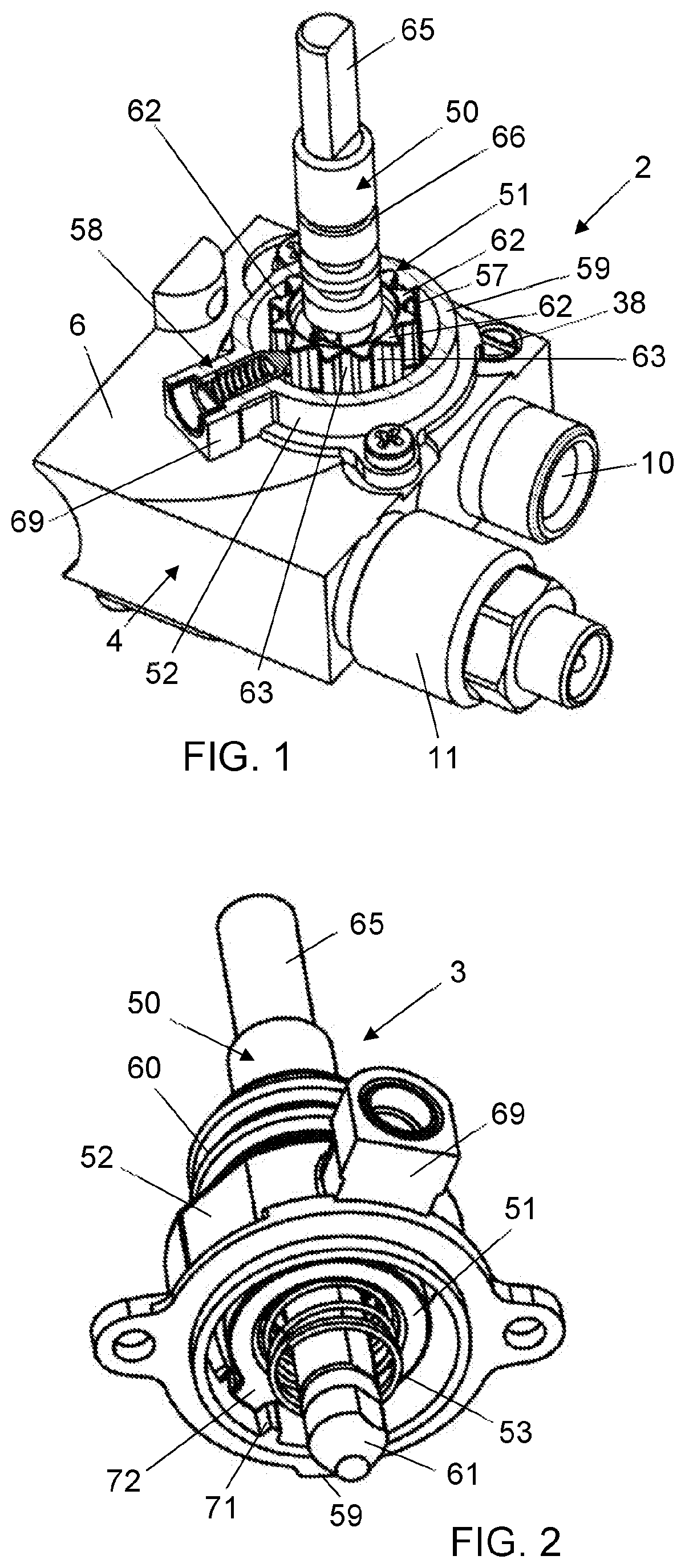
[0042]As can be seen in the figures, the improved gas valve unit 2, according to the invention, particularly for controlling / modulating the gas to be sent to a gas burner, substantially comprises a control unit 3 which is associated with a body 4.

[0043]Preferably, the body 4 is metallic, and in particular made of extruded aluminum, in which a series of gas passages and a series of chambers or cavities for housing particular functional components, which will be described in greater detail below, are obtained by mechanical machining. Appropriately, the body 4 may be defined in one piece or by several pieces joined to one another.

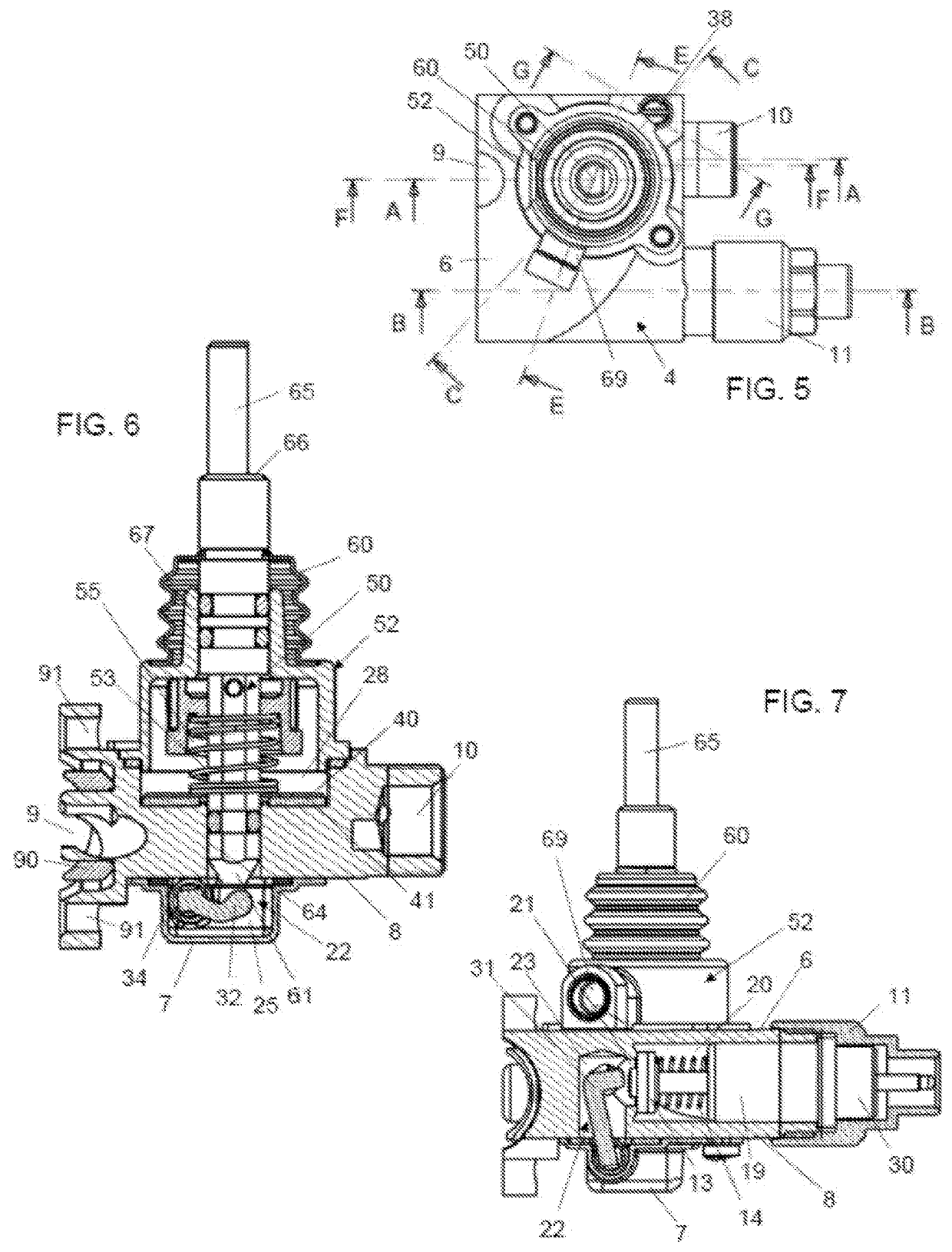
[0044]Advantageously, the body 4 has a substantially box-like shape 5, preferably of parallelepiped shape, with a first face 6, with which the control unit 3 is associated, and a second face 8, opposite and parallel to the first, with which a lid 7 is associated. Appropriately, the lid 7, which is made of aluminum sheet or other material, even non-metallic, is...


PUM


Abstract

A gas valve unit to be connected to a gas source includes a body having an inlet, a main chamber in the body communicating with the inlet and having a main outlet communicating with the outlet of the gas valve unit, a disc-shaped element in the main chamber with one or more openings putting the main chamber in communication with the main outlet hole and rotatable between a closing position, where the main outlet hole is entirely covered by the disc-shaped element, and at least two opening positions in which the one or more openings face, at least in part, the main outlet hole to enable gas passage from the main chamber to the main outlet hole via the through opening, and a control unit associated causing the snapping rotation of the disc-shaped element between the closing position and an opening position, and between the at least two opening positions.

Description

FIELD OF THE INVENTION[0001]The present invention relates to an improved gas valve unit, particularly for adjusting the gas to be sent to a gas burner.BACKGROUND OF THE INVENTION[0002]Many types of valve assemblies for regulating the flow of gas to a burner are known, such as those in which the gas passage section, and thus the gas outflow from the valve unit, is regulated by specific on-off valves which either open or close the corresponding gas outlet openings.[0003]In these known valve assemblies, on-off valves can be electromagnetically operated, e.g. individually controlled, by means of an electronic control unit, an electromagnet which is associated with each on-off valve, or may be actuated mechanically, e.g. by moving a body which in sequence causes the opening or closing of the on-off valves.[0004]In particular, WO2014139844 describes a valve unit in which the inlet is connected to the outlet by means of a plurality of on-off valves, each of which comprises a vertically mov...

Claims


Application Information

Patent Timeline
IPC IPC(8): F23N1/00
CPCF23N1/005F23K2900/05002F24C3/126F23K5/007F23K2900/05001F23N5/107F23N1/007F23N2235/16F23N2235/24
Inventor BRATTI, LORENZOLUCHETTA, PAOLONOETH, WERNER
Owner E G O ELEKTRO GERAETEBAU GMBH
Why Eureka
Try Eureka