
Time-to-digital converter and conversion method

a converter and digital technology, applied in the field of time-to-digital converter and time-to-digital conversion methods, can solve the problems of only detecting asynchronous nature of physical effects measured, and inability to detect the average distance to all objects in a scene, so as to achieve the effect of higher accuracy

Active Publication Date: 2020-04-09
SCIOSENSE BV
View PDF0 Cites 1 Cited by
  • Summary
  • Abstract
  • Description
  • Claims
  • Application Information

AI Technical Summary

Benefits of technology

This patent improves the accuracy of time-to-digital conversion by using a better timing method.

Problems solved by technology

A problem with time-to-digital converters is the asynchronous nature of the physical effects that are measured.
A major drawback is that the average distance to all objects in a scene is only detected as a single number.
A downside of this design is that by the time that the counter is being updated on the output, said edge has already progressed, so there is an inherent uncertainty for a counter value of the counter.

Method used


Image

  • Time-to-digital converter and conversion method
  • Time-to-digital converter and conversion method
  • Time-to-digital converter and conversion method

Examples


Embodiment Construction

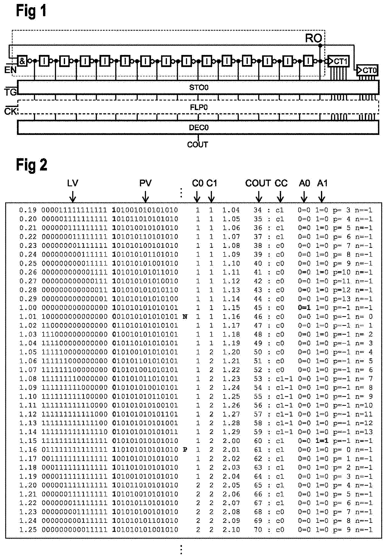
[0036]FIG. 1 shows an example embodiment of a time-to-digital converter arrangement according to the improved timing concept. The arrangement comprises a ring oscillator RO, a first counter CT0, a second counter CT1, a storage element STO0, an optional stability element FLP0 and a decoder DEC0.

[0037]In this example embodiment, the ring oscillator is formed as a 15-stage ring oscillator acting as a fine counter and consists of a two-input NAND gate followed by fourteen inverters I that may be implemented as CMOS inverters. According to the common principle of a ring oscillator, the output of the last inverter is connected to one of the inputs of the input NAND gate. A second input of said NAND gate is provided with an enable signal EN for starting respectively stopping the oscillation process within the ring oscillator RO. The number of fifteen elements within the ring oscillator RO is chosen arbitrarily for this example and can be readily varied depending on the desired application....


PUM


Abstract

A time-to-digital converter arrangement has a ring oscillator with a plurality of inverting elements and a first and a second counter coupled to the ring oscillator. The first counter is configured to increment a first counter value if a positive edge transition is present at one of the inverting elements. The second counter is configured to increment a second counter value if a negative edge transition is present at the one of the inverting elements. A storage element stores the first and the second counter value and logical states of the plurality of inverting elements. A decoder coupled to the storage element selects one of the first and the second counter value as a valid value based on an evaluation of the stored logical states, and outputs a total counter value based on the valid value and the stored logical states.

Description

BACKGROUND OF THE INVENTION[0001]The present disclosure relates to a time-to-digital converter and to a time-to-digital conversion method.[0002]A time-to-digital converter (TDC) is a device used to measure a time interval and convert it into digital output. It allows measurements of very short times at high resolution. A problem with time-to-digital converters is the asynchronous nature of the physical effects that are measured. Each measurement has to be collected for further processing.[0003]A time-to-digital converter is used in time-of-flight cameras, for example, to measure the time an emitted light signal like a laser pulse needs to travel to a reflecting object and back to the camera. A major drawback is that the average distance to all objects in a scene is only detected as a single number.[0004]A well-known technique to implement a TDC uses a ring oscillator and a counter that is being driven by this ring oscillator, in particular by a clock edge progressing through the rin...

Claims


Application Information

Patent Timeline
Patent Type & Authority Applications(United States)
IPC IPC(8): G04F10/00H03K23/00
CPCG04F10/005H03K23/005H03L7/0812H03L7/0991H03L7/089H03M1/12H03M1/1009
Inventor MAUTNER, CHRISTIANBAHNMUELLER, FRIEDRICHLAENGAUER, FRIEDRICHKAPPEL, ROBERT
Owner SCIOSENSE BV
Learn More