Assembly method and combined bivalent station for photovoltaic panels

a photovoltaic panel and workstation technology, applied in photovoltaic supports, transportation and packaging, sustainable buildings, etc., to achieve the effect of facilitating the head-tail connection, reducing the length and/or the complexity of conductive elements, and fast and economical manner

Active Publication Date: 2020-04-16
VISMUNDA
View PDF0 Cites 3 Cited by
  • Summary
  • Abstract
  • Description
  • Claims
  • Application Information

AI Technical Summary

Benefits of technology

[0066]A second aim has been that of making shingled strings that are, in turn, alternated in the direction of superimposition in order to allow a continuous production and also to facilitate the head-tail connection between adjacent strings, thus reducing the length and/or the complexity of the conductive elements that are applied in the following bussing phase.
[0067]A third aim has been that of progressively performing said superimpositions between formed cells, in an extremely fast and economical manner, and with a very high degree of precision; moreover, said superimposition is carried out shortly after the printing of the ECA on each cell, occupying an area very limited near the printer.
[0068]A fourth aim has been that of producing panels with shingled cells limiting the overturning of the cells just being printed, that is leaving the ECA adhesive facing upwards; furthermore, translations and possibilities of errors and/or misalignment between cells are minimized.
[0069]A fifth aim has been that of reducing the industrial costs for assembling a photovoltaic panel with traditional cells.
[0070]A sixth aim has been that of allowing, with the same method and the same plan

Problems solved by technology

In this way, it is possible to produce a photovoltaic panel starting from cells or portions of cells of the traditional type, with top-bottom contacts, according to the integrated assembly logic called Cell-

Method used


Image

  • Assembly method and combined bivalent station for photovoltaic panels
  • Assembly method and combined bivalent station for photovoltaic panels
  • Assembly method and combined bivalent station for photovoltaic panels

Examples


Embodiment Construction

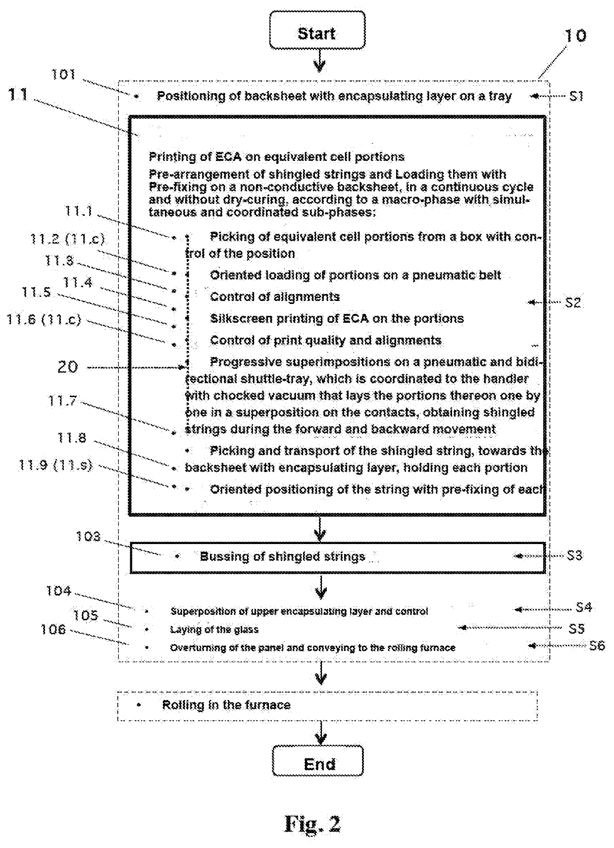
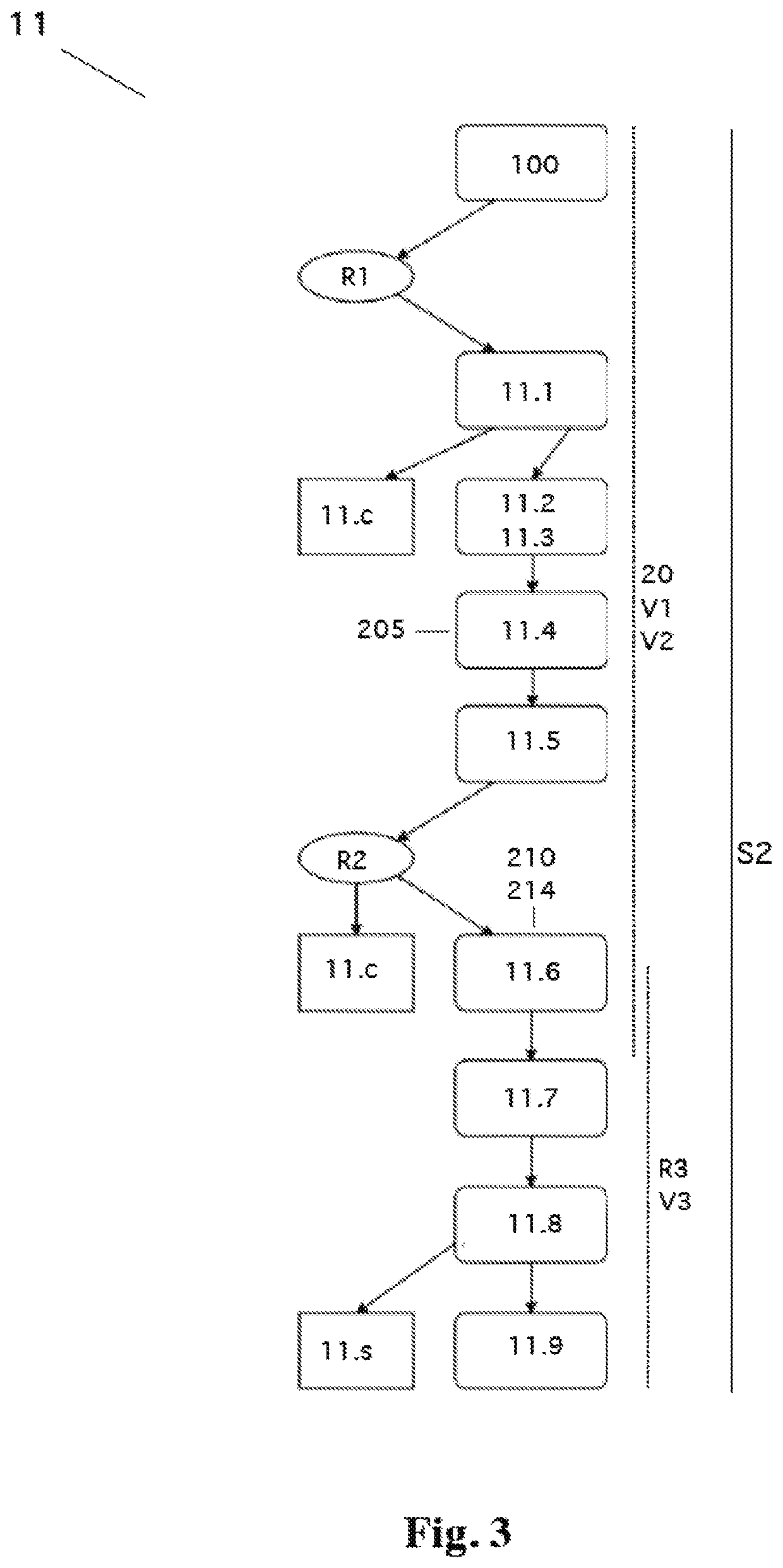
[0082]With reference also to the figures (FIGS. 2-9b), a method (10) is described, which comprises a macro-phase (11) for advantageously assembling photovoltaic panels (400) with crystalline silicon solar cells of the traditional type with top-bottom contacting, or cell portions that are identical one another (403a-403d), wherein said cells or portions are partially superimposed (404) like roof tiles for direct contacting, namely in the form called shingled. In particular, there is provided to print ECA on said cells or portions (403) and immediately pre-arrange them in a progressively superimposed way by forming shingled strings (402) in turn alternated in the direction of the head, with a particular operative logic (11.111.6) and with a particular automatic shingling apparatus (20) (FIGS. 5a-5b, 9a-9b), wherein said shingled strings (402) are pre-arrange and ready to be immediately loaded and pre-fixed (R3) on a backsheet provided with an encapsulating layer (401) (11.711.9), oper...


PUM


Abstract

An assembly method and a combined and bivalent workstation for automatically assembling photovoltaic panels, with printing of ECA on cell portions and progressive arrangement with a partial superimposition on the contacts, pre-forming shingled strings in a continuous cycle, which are ready for loading on a backsheet, without dry-curing. The method provides a macro-phase of lay-up entirely made in the station, with simultaneous and coordinated sub-phases: picking of portions with a first handler and control, oriented loading on a vacuum belt, control of positioning on the belt, printing of ECA, control of printing and positioning, progressive superimpositions on a shuttle-tray with bidirectional translation coordinated with a second handler with chocked vacuum, picking of the shingled string with a third handler, control of string alignment, loading and pre-fixing. Vision systems are integrated for the execution of said sub-phases.

Description

CROSS-REFERENCE TO RELATED APPLICATIONS[0001]Not applicable.STATEMENT REGARDING FEDERALLY SPONSORED RESEARCH OR DEVELOPMENT[0002]Not applicable.NAMES OF THE PARTIES TO A JOINT RESEARCH AGREEMENT[0003]Not applicable.INCORPORATION-BY-REFERENCE OF MATERIALS SUBMITTED ON A COMPACT DISC[0004]Not applicable.BACKGROUND OF THE INVENTIONField of the Invention[0005]This invention relates to an assembly method and to a combined and bivalent workstation for photovoltaic panels.Description of Related Art Including Information Disclosed Under 37 CFR 1.97 and 37 CFR 1.98[0006]The proposed solution finds particular application in the industrial sector of the production of photovoltaic panels, with specific reference to modern photovoltaic panels with cells in crystalline silicon mounted on a backsheet; there are provided diversified functions, but integrated to each other in such a way as to operate in a continuous cycle with high productivity, precision and versatility of use. In particular, the m...

Claims


Application Information

Patent Timeline
IPC IPC(8): H01L31/18H02S20/25H01L31/048H01L31/05B65H29/24
CPCH02S20/25H01L31/186H01L31/048B65H29/242H01L31/0508H01L31/18H01L31/0504H01L31/188Y02B10/10Y02E10/50
Inventor SPOTTI, DAVIDE
Owner VISMUNDA
Why Eureka
Try Eureka