Eureka AIR delivers breakthrough ideas for toughest innovation challenges, trusted by R&D personnel around the world.

Cascaded mirror array and scanning system thereof

Active Publication Date: 2020-04-30
NATIONAL TSING HUA UNIVERSITY
View PDF0 Cites 2 Cited by
  • Summary
  • Abstract
  • Description
  • Claims
  • Application Information

AI Technical Summary

Benefits of technology

The present invention provides a solution to the problem of high cost and heavy weight of conventional digital scanning systems by introducing a cascaded mirror array and scanning system that offers low cost and light weight. The CMA uses a support structure and position limiting structure to maintain the precision of the discretized angular positions of each array reflector. The digitized switching electrical signal merely deflects the reflector and the support determines the discretized angular positions. This reduces the cost of electrical control and allows for the use of traditional manufacturing methods for the structures and precisions.

Problems solved by technology

However, these traditional scanners are quite expensive and huge, and not suitable for use in UAVs.
Particularly, in a consideration of load and energy consumption, these traditional scanners are not suitable for small-sized UAVs.
However, in order to maintain precision, these devices still require complex circuits, built-in sensors, and driving control scheme for specific devices.
Due to the complexity of the device structure, the manufacturing process and the need to use MEMS plants, a complete MEMS system including devices, driver electronics, and control software still costs a few thousand US dollars.
However, precision prisms are still needed in each stage and they are not cheap to make.
Another issue is that polarization switching efficiency and light transmission through a LC cell are both limited.
Therefore, light beam quality after passing many stages of LC cells and prisms could deteriorate, especially in later stages corresponding to wide angle deflections.
However, the limitation is that the light has to propagate within the thin, planar wave guide, which makes scanning in a perpendicular second direction difficult.
To connect two devices for 2D scanning could also be difficult.
In addition, environmental and field operation issues are also important factors to consider.
Therefore, existing products or technologies still cannot quite satisfy the low-cost and light-weight requirements in commercial or consumer UAV applications.

Method used


Image

  • Cascaded mirror array and scanning system thereof
  • Cascaded mirror array and scanning system thereof
  • Cascaded mirror array and scanning system thereof

Examples


example prototype

[0055]A 4-bit CMA scanner prototype was built as an example of implementation details, to demonstrate the feasibility of the proposed concept and to show that the proposed system can be made from common materials in a regular lab without using microfabrication processes.

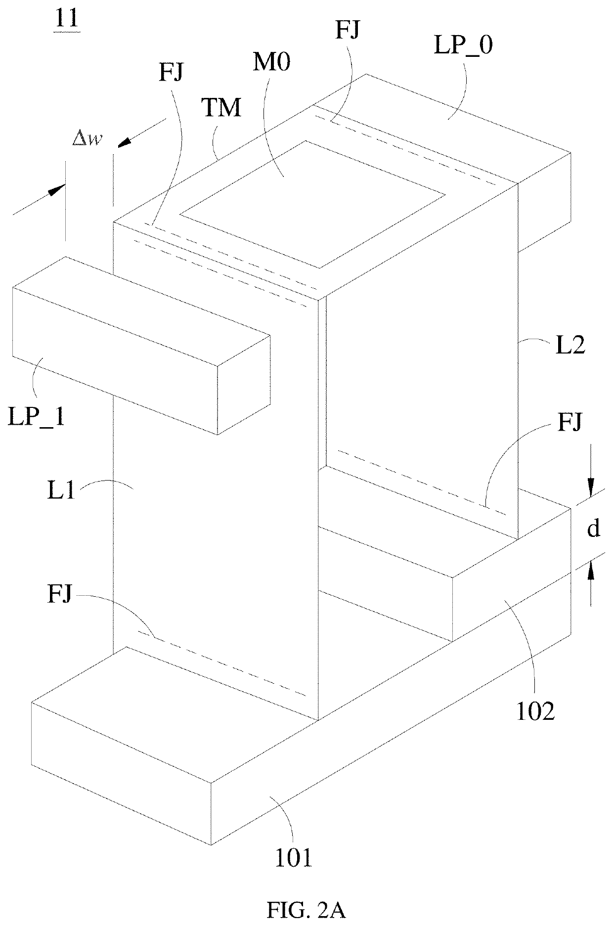
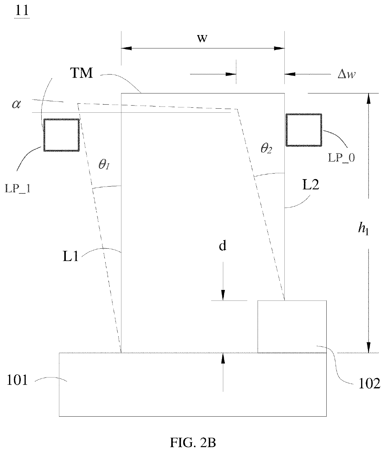
[0056]FIG. 5A shows a prototype of a single reflector unit with the ULT mechanism and FIG. 5B shows its construction in a side view. The reflector M0 is a first surface mirror with a size of 3×3×1 mm. The uneven-leg tilting mechanism 13 includes a plastic base BB, a first leg L1, a second leg L2, and a top link TM. The reflector M0 is disposed on the top link TM. In the embodiment, the length w of the top link TM is 6 mm, the length h1 of the first leg L1 is 10 mm. The top link and the legs has a width of 5 mm and is basically made from stacking three layers of different materials. The flexural joints were made of a layer of laminated polyester films PF of a thickness of 0.05 mm. Three pieces of PET sheet material of...


PUM


Abstract

A Cascaded Mirror Array optical scanning system applies an array of reflectors, with each reflector (called array reflector for convenience) movable between discretized angular positions and independently switched by digitized electrical signals, to process a light beam by cascaded reflections to generate desired deflection angle of the beam. The precision of the discretized angular positions of each array reflector is maintained by a support structure, which supports the reflector while allowing it to rotate or tilt, and a set of positioning limiting structure, which limits the allowable angular position of the array reflector between a finite number of angular positions corresponding to the discretized angular positions.

Description

CROSS-REFERENCE TO RELATED APPLICATION[0001]This application claims the priority benefit of Taiwan Patent Application No. 107138562, filed on Oct. 31, 2018, in the Taiwan Intellectual Property Office, the disclosure of which is incorporated herein in its entirety by reference.BACKGROUND OF THE INVENTION1. Field of the Invention[0002]The present invention relates to a light beam scanning system, more specifically, a precision light beam scanning system of simple construction, fast response, high impact resistance and low cost based on non MEMS fabrication processes.2. Description of the Related Art[0003]Vector scanning technology, also called point-to-point scanning or random-access scanning, has applications in vector graphics, laser marking, laser machining, laser additive manufacturing, LIDAR, and optical routing. Another emerging market is laser tracking / communication for UAVs (Unmanned Aerial Vehicles), automobiles, aircrafts and satellites, because the exponential rise of UAVs ...

Claims


Application Information

Patent Timeline
IPC IPC(8): G02B26/10G02B26/08
CPCG02B26/0816G02B26/101G02B26/105
Inventor TSAO, CHE-CHIHCHEN, CHIH-HSIANG
Owner NATIONAL TSING HUA UNIVERSITY
Why Eureka
Eureka Blog
Learn More