Apparatus for Cleaning Industrial Plants

a technology for industrial plants and apparatus, applied in the direction of manipulators, paper-making machines, textiles and paper, etc., can solve the problems of high energy expenditure, high cost, and inefficiency of machinery and production stops for cleaning operations, and achieve the effect of reducing or eliminating

Inactive Publication Date: 2020-05-07
PNP DISCOVER SRL
View PDF0 Cites 8 Cited by
  • Summary
  • Abstract
  • Description
  • Claims
  • Application Information

AI Technical Summary

Benefits of technology

[0013]The main object of the present invention is therefore to propose a robotized apparatus for cleaning industrial plants capable of eliminating, or at least greatly reducing, the aforementioned drawbacks.
[0014]Another object of the present invention is to propose a robotized apparatus for cleaning industrial plants capable of performing an accurate cleaning of the entire installation volume of the industrial plant.
[0017]Another object of the present invention is to propose a robotized apparatus capable of carrying out the cleaning during the production itself, thus increasing the efficiency of the system.

Problems solved by technology

Many industrial machinery and plants, such as machine tools for metal, wood or plastic chip removal, as well as paper processing plants, during their operation generate waste or powders of various grain size spreading in the air and then settling on the machines themselves and in the other surrounding structures and equipments, causing inefficiencies of the machinery and production stops for carrying out cleaning operations.
These systems are very cumbersome because they involve the presence of large volumes for the passage of air and the use of considerable suction power with a lot of air flow so that they could create a force sufficient to move the powders suspended in the air.
This obviously also involves a large electrical power need to supply the aforementioned suction systems, which translates into a high energy expenditure and therefore a high cost.
They are also known systems which provide for the installation of suction mouths directly in the areas where the material is processed, in this case the power of the vacuum pumps can be reduced, but the presence of the suction system in the proximity of the processing area disadvantageously makes the machine inaccessible.
In general, all conventional cleaning systems have a limited efficiency and the machines need to be cleaned on all neighboring surfaces therefore this operation is manually performed.
In fact, the paper fibers are detached from the tape and deposited everywhere creating a cluster that negatively affect the quality and efficiency of the process.
These cluster of paper dust are mainly to be eliminated in order to reduce the risk of fire and for this reason expensive and complex dust extraction systems are necessary on the paper processing lines.
All the boxes inserted in the line create accessibility problems both for the use and for the maintenance of the machines themselves, often they are made with systems that allow them to be moved by sliding on guides with manual or automatic actuators, but the plants end up being increasingly complex and the spaces for using the machine are still sacrificed.
Moreover, the dust can not be captured in its entirety as the paper itself, which is the vehicle, passes through all the devices of the processing line, distributing both inside and outside the machines and on the floorings.
These create safety problems for the operators, since they have the risk of breathing those suspended airborne dust, which increase during the cleaning phase itself.
Even during the dirt removal phase, there is the risk of being hit by a reaction to the pushing force they exert, for example by acting with compressed air on the dirt itself.
Still, in plants where paper is transformed there is the problem of dust deposited on all the air structures such as pipes and structural beams, which represents a real problem in case of fire.
This operation has several drawbacks such as the temporary pollution of the air, which is harmful to the operators, and the subsequent deposition of all the dust on the surfaces on the ground, which must then be removed.

Method used


Image

  • Apparatus for Cleaning Industrial Plants
  • Apparatus for Cleaning Industrial Plants
  • Apparatus for Cleaning Industrial Plants

Examples


Embodiment Construction

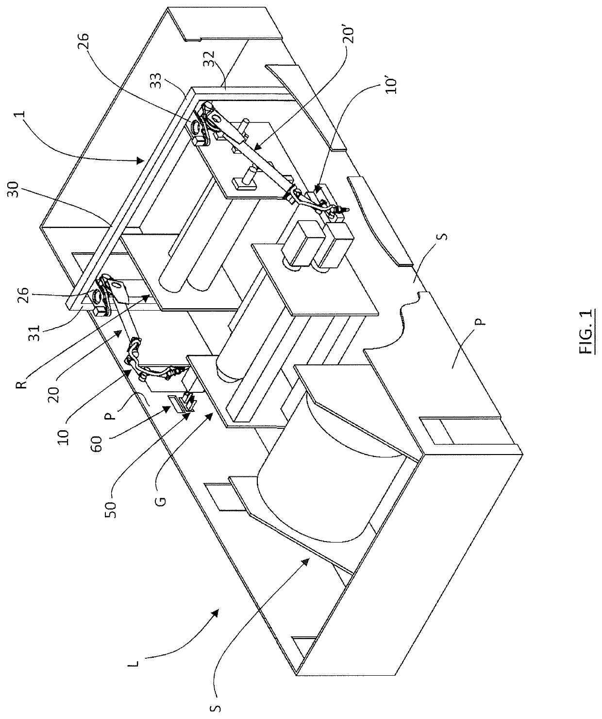
[0040]With reference to the aforementioned figures, it is below described an exemplary embodiment of an apparatus for cleaning industrial plants according to the present invention, installed in a line for converting tissue to obtain toilet paper or towels.

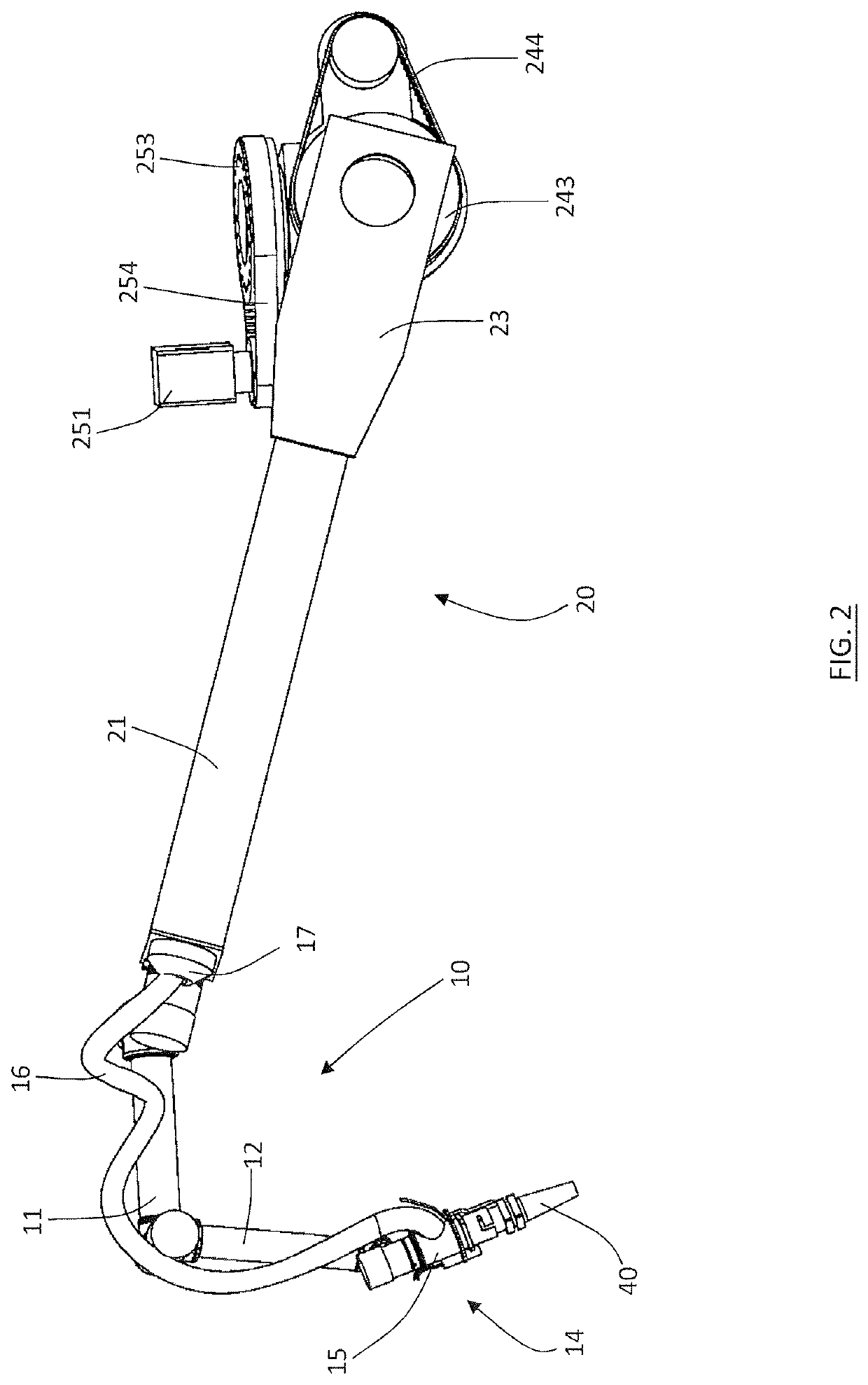
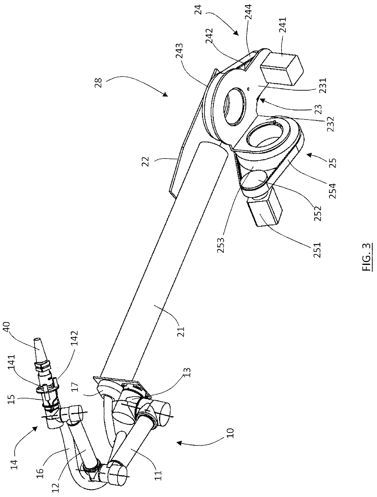
[0041]With reference to FIG. 1, a line for converting tissue, L, includes, for example, an unwinding device, S, for unwinding mother coils, an embossing machine, G, for obtaining reliefs by pressing between rollers, a rewinding boring machine, R, for making transversal perforations for obtaining the splits and for the rewinding process in diameters for the finished product, and an apparatus for cleaning, 1, according to the present invention, comprising two robotic arms, 10, 10′, and related moving elements consisting of oscillation assemblies, 20, 20′.

[0042]The portal 30 comprises two uprights, 31, 32, aligned transversely to the sides of the line L which support a crosspiece 33, which joins them transversely crossing the line L a...


PUM


Abstract

An apparatus (1) for cleaning industrial plants comprises a robotic arm to a working head of which are associated suction members suitable for sucking powders and working fragments inside a working volume in which a processing industrial plant is installed (L). The working head comprises an extensible manifold for moving the suction mouth (40) away from the end of the robotic arm thus allowing to reach remote positions and moreover the robotic arm (10) is mounted on moving members, for example a portal, which allow the robotic arm to be moved at different useful working volumes so that an accurate cleaning can be performed on a very large overall volume.

Description

TECHNICAL FIELD[0001]The present invention relates to an apparatus and a method for cleaning industrial plants in which it is processed or transformed a material which, during processing or transformation, produces powders as a residue of the process.[0002]In a specific embodiment, the invention relates to an apparatus for cleaning plants for converting paper.STATE OF THE ART[0003]Many industrial machinery and plants, such as machine tools for metal, wood or plastic chip removal, as well as paper processing plants, during their operation generate waste or powders of various grain size spreading in the air and then settling on the machines themselves and in the other surrounding structures and equipments, causing inefficiencies of the machinery and production stops for carrying out cleaning operations.[0004]The known art of the sector comprises various methods and apparatuses for cleaning by suction, for example in the field of wood processing, the powders and scraps are removed from...

Claims


Application Information

Patent Timeline
Patent Type & Authority Applications(United States)
IPC IPC(8): B25J11/00B08B5/04B25J15/00B25J9/16B25J19/04B25J13/08B08B5/02
CPCB25J15/0019B25J9/1679B08B5/02B25J19/04B08B5/04B25J13/085B25J11/0085B25J13/087D21F1/32D21F11/14D21G3/00
Inventor PATERNI, ALESSANDRO
Owner PNP DISCOVER SRL
Why Eureka
Try Eureka