Carbon materials for improving performance of lead acid batteries
a lead acid battery and carbon material technology, applied in the direction of cell components, basic electric elements, electrical equipment, etc., can solve the problems of battery failure, unsatisfactory gas evolution, water loss, etc., and achieve better static charge acceptance, improved hybrid pulse power profile, and reduced recharge time
- Summary
- Abstract
- Description
- Claims
- Application Information
AI Technical Summary
Benefits of technology
Problems solved by technology
Method used
Image
Examples
example 1
Preparation of Lead Acid Paste
[0339]Lead-acid pastes were prepared utilizing an Eirich mixer with leady oxide (20% free-lead content), sulfuric acid, and additives as shown in Table 1 below. Resulting pastes were applied to PbCaSn alloy grids, humid cured at 50° C. and 98% humidity for 24 hours, and dry cured at 60° C. and 0% humidity for 24 hours. NAM and PAM compositions were independently formed through tank formation profiles. Lead-acid 2V cells consist of 1 NAM electrode sandwiched between 2 PAMs with porous polypropylene separator and 1.27 s.g. H2SO4 electrolyte. Cells are placed in a 25° C. water bath for the duration of electrochemical testing.
TABLE 1Components of lead acid pastes used in cells for 2V devicesTestSample# of cellsNAMPAMI-16No Carbon MaterialNo additiveI-2101.0 wt% Carbon Material 1No additiveI-32No Carbon Material1.0 wt% tetrabasic lead sulfateI-461.0 wt% Carbon Material 11.0 wt% tetrabasic lead sulfateI-54No Carbon Material1.0 wt% tetrabasic lead sulfate,3.0 ...
example 2
High Rate Partial State of Charge Cycle Testing
[0340]Cells prepared according to Example 1 were initially tested for a C / 20 capacity followed by either a constant current (CC) or constant voltage (CV) High Rate Partial State of Charge (HRPSoC) test.
[0341]CC-HRPSoC discharges the cell to 50% state of charge and is cycled using a 60 second 2C discharge step and 60 second 2C charge step until the total voltage reaches 1.7V. After reaching 1.7V, the cell was recharged and a subsequent C / 20 capacity test was conducted. If the new capacity was >70% the initial C / 20 capacity, the CC-HRPSoC cycling was restarted.
[0342]CV-HRPSoC testing similarly discharged the cell to 50% state of charge and cycled using a 60 second 2C discharge, but then utilized a 60 second 2.4V charging step until the total voltage reached 1.7V. After reaching 1.7V, the cell was recharged and a subsequent C / 20 capacity test was conducted. If the new capacity was >70% the initial capacity, the CV-HRPSoC cycling was restar...
example 3
Motive Cycling
[0348]A motive-style duty cycling test was used to cycle between 20% and 80% of the cell capacity at relatively slow rates. Cells tested were prepared according to the components listed in Table 4, below:
TABLE 4Components of electrodesComponentTest Sample III-1Test Sample III-2Leady Oxide98.1 wt%98.1 wt%Barium Sulfate 0.6 wt% 0.6 wt%Lignin 0.2 wt% 0.2 wt%Carbon Black 0.1 wt% 0.1 wt%Carbon Material 1— 1 wt%Agglomerated 1 wt%—Carbon 1
[0349]All electrodes were hand-pasted, humid cured at 50° C. and 98% RH for 24 hours, and tank formed. All PAMs consisted of 1% Tetra L2 seeding and 3% PN-20 red lead. Cells were assembled with H2SO4 (1.27 specific gravity) and tested on a Maccor using an electrochemical screening profile prior to motive duty cycling.
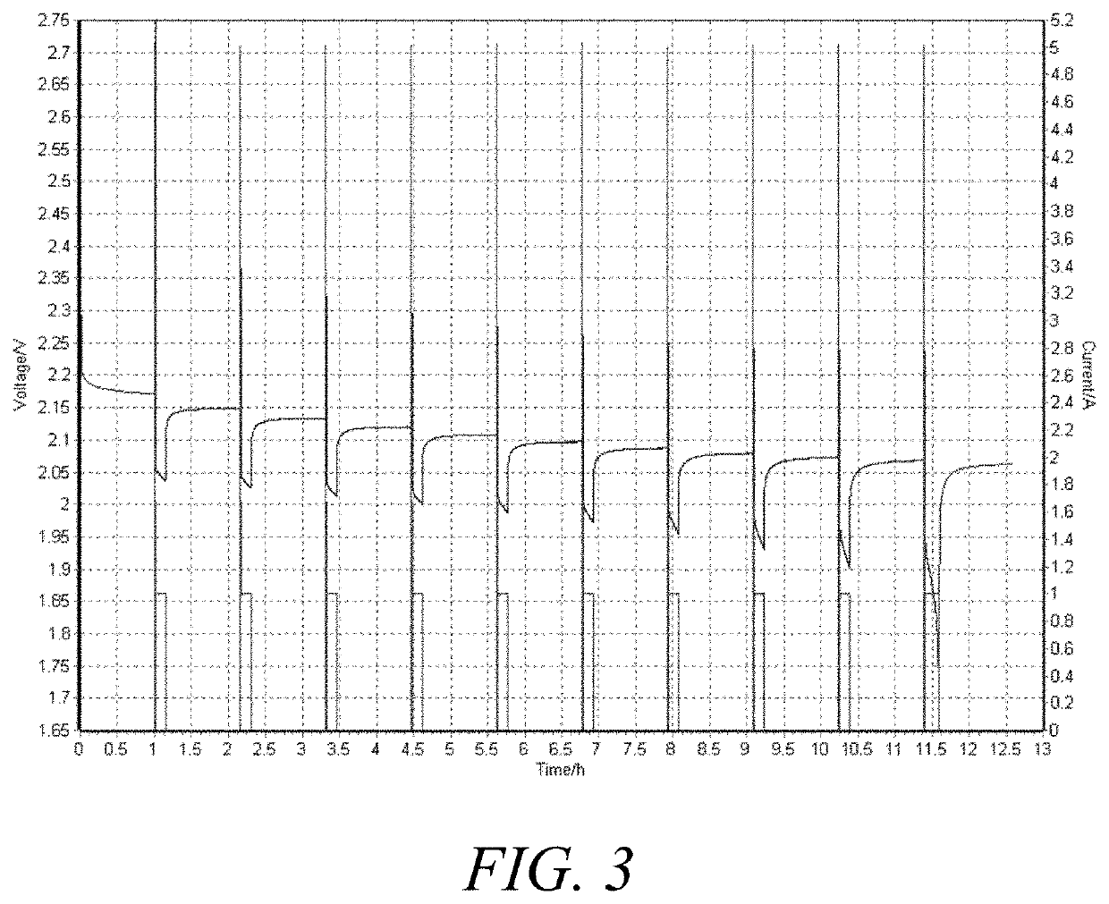
[0350]The Motive Cycling Test followed the following steps:
[0351]1. Rest for 1 hour at open circuit voltage
[0352]2. Discharge at 800 mA until discharge voltage drops to 1.7 V and record initial capacity
[0353]3. Charge at 2.6...
PUM
| Property | Measurement | Unit |
|---|---|---|
| particle size | aaaaa | aaaaa |
| BET specific surface area | aaaaa | aaaaa |
| BET specific surface area | aaaaa | aaaaa |
Abstract
Description
Claims
Application Information
 - R&D
- Intellectual Property
- Life Sciences
- Materials
- Tech Scout
- Unparalleled Data Quality
- Higher Quality Content
- 60% Fewer Hallucinations
Browse by: Latest US Patents, China's latest patents, Technical Efficacy Thesaurus, Application Domain, Technology Topic, Popular Technical Reports.
© 2025 PatSnap. All rights reserved.Legal|Privacy policy|Modern Slavery Act Transparency Statement|Sitemap|About US| Contact US: help@patsnap.com


