Drive control apparatus for switching element

a control apparatus and switching element technology, applied in electronic switching, pulse technique, semiconductor devices, etc., can solve the problems of difficult to determine the abnormal operation, difficult to follow the control of a transient change, and inability to detect accurate current, etc., to achieve the effect of reducing current capacity

Active Publication Date: 2020-05-07
DENSO CORP
View PDF7 Cites 8 Cited by
  • Summary
  • Abstract
  • Description
  • Claims
  • Application Information

AI Technical Summary

Benefits of technology

[0012]The present disclosure aims at providing a drive control apparatus for a switching element, the apparatus being capable of suppressing lifetime reduction of the switching element by rapidly detecting overcurrent with a simple and inexpensive configuration.
[0014]With the adoption of the above configuration, since the transient characteristic absorbing circuit can absorb the transient characteristic generated when the switching element is turned on, the determination circuit can determine an overcurrent or a short-circuit state of the switching element from an output of the sense element without waiting for completion of the transient characteristic. This can prevent the current from continuing to flow in the switching element until the determination due to the overcurrent or the short-circuit, and thus, a configuration having a reduced current capacity can be used as the switching element.

Problems solved by technology

However, since conventionally, with the configuration of a current detection circuit of such a switching element, when the current is detected, a sense ratio deviates due to sense resistance, capacitance characteristics of the sense element, or the like, a problem that an accurate current cannot be detected is found.
However, with this configuration, a problem is found in which an external circuit is required and further it is difficult to follow the control of a transient change.
However, with this configuration, since the gate voltage may change due to a load situation even during normal operation and a gate voltage wave shape is different every time also during abnormal operation, a problem that it is difficult to determine the abnormal operation is also found.
However, since the setting of capacitor for cancelling the capacitance variation amount is difficult and the number of additional parts is large, a problem that practical adoption is difficult is found.

Method used


Image

  • Drive control apparatus for switching element
  • Drive control apparatus for switching element
  • Drive control apparatus for switching element

Examples


first embodiment

[0061]The first embodiment will be described below with reference to FIG. 1 to FIG. 5.

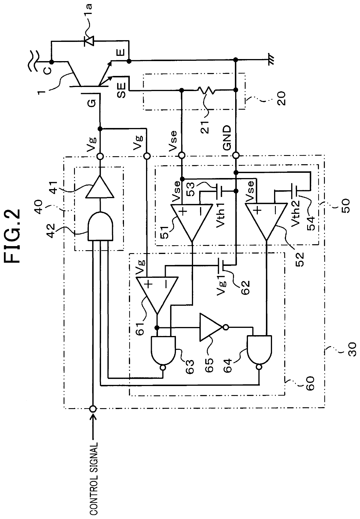
[0062]In the first embodiment, a first system will be described that monitors a gate voltage to rapidly detect a state, such as overcurrent or short-circuit, of an IGBT 1, which is a switching element, and allow a protection operation to be performed.

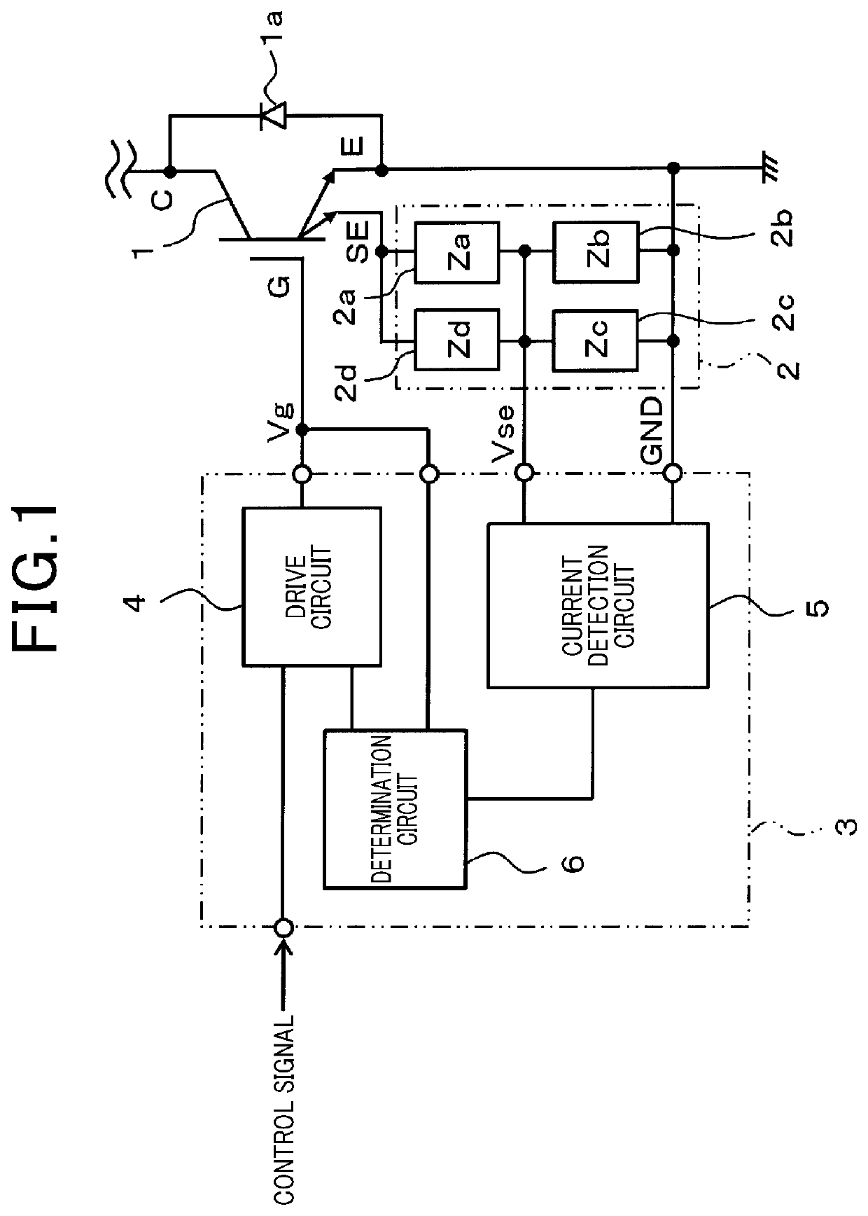
[0063]In FIG. 1 that shows a basic configuration of the first system, the IGBT 1 integrally includes a main element and a sense element and the main element and the sense element are connected with collectors C and gates G in common. With respect to an emitter E of the main element, the sense element has a sense emitter SE provided to detect a current proportional to a current flowing in the main element. In addition, in the IGBT 1, a diode 1a is connected between the collector C and the emitter E. The diode 1a may be incorporated in the IGBT 1 or provided externally.

[0064]In the IGBT 1, the collector C to emitter E is connected between a load, not sho...

second embodiment

[0085]FIG. 6 shows the second embodiment and hereinafter illustrates parts different from the first embodiment. In this embodiment, as a configuration to detect the gate voltage Vg of the IGBT 1, as shown in FIG. 6, provided is a determination circuit 60a using a voltage dividing circuit of resistors 66 and 67. In the configuration, a series circuit of the resistors 66, 67 is connected between the gate G and the ground, and the common connection point thereof is input to the third comparator 61 of the determination circuit 60a.

[0086]The gate voltage Vg is divided by the resistors 66, 67 and is input to the third comparator 61 as a voltage Vga proportional to the gate voltage Vg. In accordance with this configuration, the reference power supply 62 sets Vg2 instead of the switching voltage Vg1.

[0087]Hence, also with the second embodiment described above, effects similar to those of the first embodiment can be obtained. In addition, since the gate voltage Vg is divided by the resistor...

third embodiment

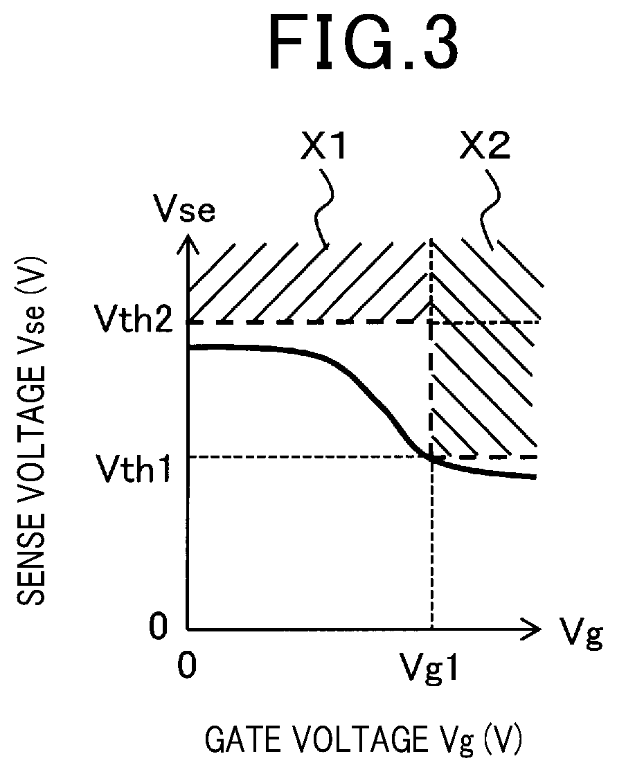
[0088]FIG. 7 shows the third embodiment, which is different from the first embodiment in that a region of the gate voltage Vg is divided into three regions by Vg1 and Vg2, and in the respective three regions, threshold voltages Vth1, Vth2, and Vth3 of the sense voltage Vse are set.

[0089]As shown in FIG. 7, accuracy in detecting an abnormality is enhanced by finer setting of the threshold voltage in consideration of the relation between the gate voltage Vg and a standard sense voltage Vse. In this case, the conditions that the value of the sense voltage Vse indicates an overcurrent or a short-circuit abnormality are the following expressions (a) to (c) depending on the value of the gate voltage Vg. These are conditions for cases corresponding to regions indicated by hatched lines in FIG. 7. In the determination circuit 60, it can be configured so that three comparators are provided and are switched depending on the gate voltage Vg.

When Vg≥Vg1,Vse>Vth3  (a)

when Vg1≥Vg≥Vg2,Vse>Vt...


PUM


Abstract

A drive control apparatus for a switching element drives a switching element including a sense element, and includes a drive circuit that provides a gate driving signal to the switching element, a transient characteristic absorbing circuit that absorbs a transient characteristic of the sense element when the switching element is turned on, and a determination circuit that determines an overcurrent or a short-circuit state of the switching element from an output of the sense element.

Description

CROSS-REFERENCE TO RELATED APPLICATION[0001]The present application claims the priority based on Japanese Patent Application No. 2016-101408 filed in the Japan Patent Office on May 20, 2016, and Japanese Patent Application No. 2017-93059 filed in the Japan Patent Office on May 9, 2017, and the entire description of which is incorporated herein by reference.TECHNICAL FIELD[0002]The present disclosure relates to a drive control apparatus for a switching element.BACKGROUND ART[0003]In a power semiconductor switching element, there is one that includes a sense element for monitoring a current flowing in itself. In such a switching element, a current value flowing in the switching element is estimated from a voltage of a sense resistor connected to the sense element. This enables protection operation when an overcurrent or a short-circuit of the switching element has occurred and, can reduce an element size by reducing a current capacity of the switching element.[0004]In addition, in ord...

Claims


Application Information

Patent Timeline
Patent Type & Authority Applications(United States)
IPC IPC(8): H03K17/082
CPCH03K17/0828H03K2217/0027H03K17/18H03K17/0822
Inventor INOUE, TAKESHI
Owner DENSO CORP
Why Eureka
Try Eureka