

Process cartridge and image forming apparatus
- Summary
- Abstract
- Description
- Claims
- Application Information
AI Technical Summary
Benefits of technology
Problems solved by technology
Method used
Image

Examples
embodiment 1
Image Forming Apparatus
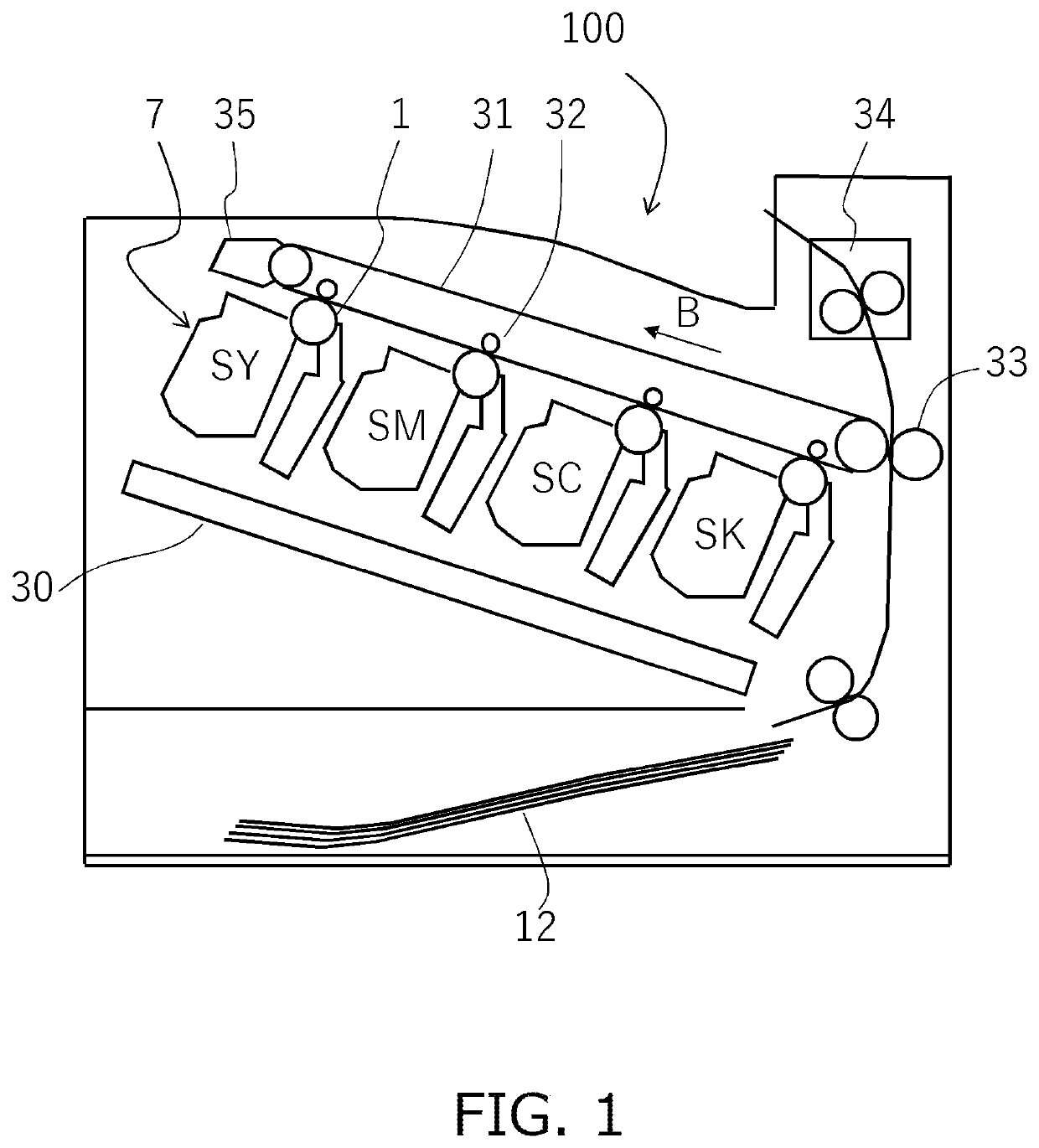
[0045]The overall configuration of an embodiment of one electrophotographic image forming apparatus will be described with reference to FIG. 1. FIG. 1 is a schematic cross-sectional view of an image forming apparatus 100 according to an embodiment of the present invention. Examples of the image forming apparatus to which the present invention can be applied include a copying machine, a printer and the like using an electrophotographic system. In the case described herein, the present invention is applied to a full color laser beam printer using a tandem system and an intermediate transfer system as the image forming apparatus 100 of the present embodiment.
[0046]The image forming apparatus 100 can form a full-color image on a recording material (for example, recording paper, plastic sheet, cloth, and the like) according to image information. The image information is inputted to the image forming apparatus main body from an image reading device connected to the ...
example
[0243]Hereinafter, the charging roller and toner used in Examples and Comparative Examples of the present invention will be described.
[0244]In the following description, the numbers 2-1 and 2-2 attached to the charging roller and the numbers 1 to 6 attached to the toner are for distinguishing the types thereof. These are different from the reference numerals “2” and “10” in the drawings or those given in other explanations referred to the drawings.
Charging Roller 2-1
[0245]As shown in FIG. 5B, the elastic layer 222 of the charging roller 2-1 is formed of domains 212 that form an island portion and a matrix 211 that forms a sea portion.
[0246]Method for Producing Charging Roller
[0247]Hereinafter, the present invention will be described more specifically with reference to production examples and Examples, but the present invention is not limited thereto in any way. In addition, all the parts in the following blends are on the mass basis.
[0248]A total of 100 parts of ethylene-propylene-d...
PUM
| Property | Measurement | Unit |
|---|---|---|
| Fraction | aaaaa | aaaaa |
| Force | aaaaa | aaaaa |
| Pressure | aaaaa | aaaaa |
Abstract
Description
Claims
Application Information