

Curable material and method for molding said thermally curable material
a curable material and thermosetting technology, applied in the direction of coatings, etc., can solve the problem of not obtaining sufficient durability, achieve excellent continuous moldability, prevent the spread of sealant, and suppress the generation of burrs
Pending Publication Date: 2020-05-21
IDEMITSU KOSAN CO LTD
View PDF3 Cites 3 Cited by
- Summary
- Abstract
- Description
- Claims
- Application Information
AI Technical Summary
Benefits of technology
The present invention provides a thermosetting material that can prevent unfilled sections, voids, and burrs when molded onto a lead frame, while also having excellent continuous moldability. Additionally, the material can prevent sealant from spreading and light leakage when sealing a light-emitting element section onto a lead frame, and has low reflectivity when non-lighting and a large contrast ratio between lighting and non-lighting, as well as excellent heat and light resistance. The material also has good storability at normal temperature.
Problems solved by technology
But, there is involved such a problem that when applied to a light source requiring light emission at a high luminance, sufficient durability is not obtained.
Method used
View moreImage
Smart ImageViewing Examples

Examples
examples
[0229]The present invention is hereunder described in more detail by reference to Examples, but it should be construed that the present invention is not limited by the Examples.
Login to View More PUM
| Property | Measurement | Unit |
|---|---|---|
| Temperature | aaaaa | aaaaa |
| Temperature | aaaaa | aaaaa |
| Time | aaaaa | aaaaa |
Abstract
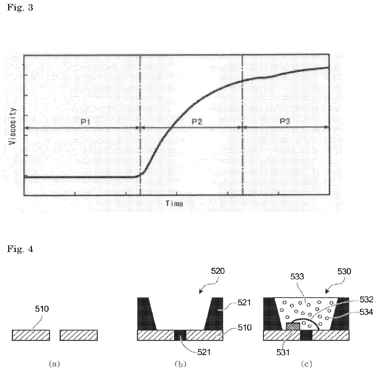
The present invention provides a thermosetting material, which contains the following components (A) to (C) and which, when measured with a rotational viscometer at a constant shear rate (JIS K7117-2:1999), exhibits a viscosity at 25° C. and 10 s1 of 5 Pa·s or more and 200 Pa·s or less and, when measured with a rotational viscometer at a constant shear rate in the same manner as above, exhibits a viscosity at 25° C. and a shear rate of 100 s1 of 0.3 Pa·s or more and 50 Pa·s or less. (A): a (meth) acrylate compound in which a substituted or unsubstituted alicyclic hydrocarbon group having 6 or more carbon atoms is ester-bonded, and which, when measured with a rotational viscometer at a constant shear rate in the same manner as above, exhibits a viscosity of 5 to 300 mPa·s as a viscosity measured at 25° C. and 10 to 100 s−1; (B): spherical silica; and (C): a black pigment.
Description
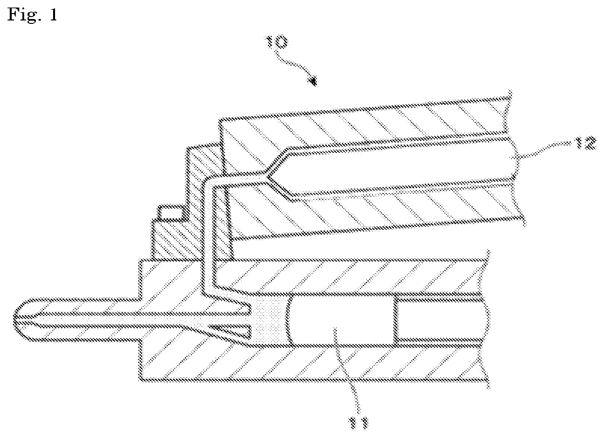
TECHNICAL FIELD[0001]The present invention relates to a thermosetting material and a method for molding the thermosetting material.BACKGROUND ART[0002]An optical semiconductor light-emitting device utilizing an optical semiconductor, such as a light-emitting diode (LED), that has been widespread in recent years is normally produced by a method in which an optical semiconductor is fixed on a lead frame of a molded body obtained by integrally molding a synthetic resin as a housing material in the shape of a concave on a lead frame, followed by sealing with a sealing material, such as an epoxy resin or a silicone resin.[0003]The LED is used as an LED for a display application capable of securing high visibility even under sunlight, a low reflective optical semiconductor light-emitting device or automotive head light for a sensor such that its presence is not obtrusive, and the like.[0004]As characteristics required therefor, there are requirements such that a contrast ratio that is a r...
Claims
Login to View More Application Information
Patent Timeline
 IPC IPC(8): C08F20/18C08K3/04C08K3/36B29C45/00C08K7/18B29C45/02C08K3/22C08K9/06B29K33/04B29K105/00B29K507/04B29K509/08
CPCC08F20/18C08K3/22B29K2105/0002C08K2201/014B29K2509/08C08K2201/003C08K9/06B29C45/02B29C45/0001C08K3/04C08K7/18B29K2033/04B29K2105/0032B29K2507/04C08K2201/011C08K2003/2241C08K3/36C08F2/44C08K3/013C08K2003/2237C08F222/102B29C45/34C08L33/06C08F220/1811C08F220/1812C08F220/325C08F220/1818C08F222/103B29C45/00C08K2201/005
InventorOBATA, YUTAKAMORI, HARUHIKO
OwnerIDEMITSU KOSAN CO LTD