
Brain activity analyzing apparatus, brain activity analyzing method, program and biomarker apparatus

Active Publication Date: 2020-05-28
ATR ADVANCED TELECOMM RES INST INT
View PDF0 Cites 4 Cited by
  • Summary
  • Abstract
  • Description
  • Claims
  • Application Information

AI Technical Summary

Benefits of technology

The present invention describes a device and method for analyzing brain activity to determine if it is healthy or diseased. This invention also includes a biomarker device and program for identifying specific brain patterns associated with neurological or mental disorders.

Problems solved by technology

However, it is not necessarily clear how the default mode network relates to the cognitive function, or how the correlations of functional connections among brain regions relates to the above-described neurofeedback.

Method used


Image

  • Brain activity analyzing apparatus, brain activity analyzing method, program and biomarker apparatus
  • Brain activity analyzing apparatus, brain activity analyzing method, program and biomarker apparatus
  • Brain activity analyzing apparatus, brain activity analyzing method, program and biomarker apparatus

Examples


first embodiment

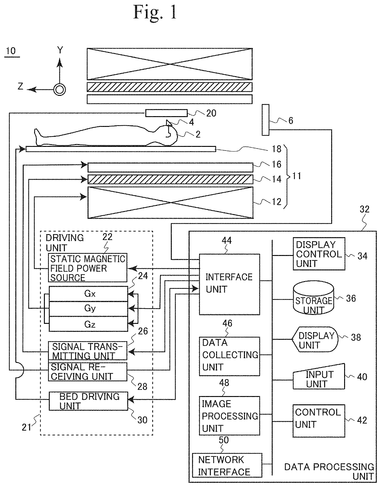
[0104]FIG. 1 is a schematic diagram showing an overall configuration of an MRI apparatus 10.

[0105]Referring to FIG. 1, MRI apparatus 10 includes: a magnetic field applying mechanism 11 applying a controlled magnetic field to, and irradiating with RF (Radio Frequency) wave, an ROI of a subject 2; a receiving coil 20 receiving a response wave (NMR signal) from subject 2 and outputting an analog signal; a driving unit 21 controlling the magnetic field applied to subject 2 and controlling the transmission / reception of RF wave; and a data processing unit 32 configuring a control sequence of driving unit 21 and processing various data signals to generate an image.

[0106]Here, the central axis of a cylindrical bore in which subject 2 is placed is regarded as a Z-axis, and a horizontal direction orthogonal to the Z-axis and the vertical direction orthogonal to the Z-axis are defined as X-axis and Y-axis, respectively.

[0107]In MRI apparatus 10 having such a configuration, because of the stati...

second embodiment

[0368]In the configuration described in the first embodiment, the brain activity measuring device (fMRI device) measures data of brain activities obtained at a plurality of measuring sites and based on the brain activity data, generation of biomarkers and estimation (prediction) of diagnosis labels by the biomarkers are realized by processing by one computer or by distributed processing.

[0369]It is noted, however, that i) measurement of brain activity data for training a biomarker through machine learning (data collection), ii) the process of generating a biomarker through machine learning and the process of estimating (predicting) diagnosis labels by the biomarker for a specific subject (estimation process), and iii) measurement of brain activity data of the specific subject above (measurement of subject's brain activities), may be executed in a distributed manner at different sites.

[0370]FIG. 22 is a functional block diagram showing an example when data collection, the estimating ...


PUM


Abstract

[Object] An object is to provide a brain activity analyzing method for realizing a biomarker using brain function imaging for neurological / mental disorders.[Solution] From data of resting-state functional connectivity MRI obtained by measuring groups of healthy subjects and patients, a correlation matrix of degrees of activities among prescribed brain regions is derived. By a sparse canonical correlation analysis (SCCA) of attributes of subjects and the correlation matrix, elements of correlation matrix that connect to canonical variables corresponding only to the diagnosis label are extracted. By sparse logistic regression (SLR) during Leave-One-Out Cross Validation of a first sum-set of elements of correlation matrix obtained as a result of feature extraction by a sparse regularized canonical correlation analysis, a second sum-set of elements of the correlation matrix is extracted. By discrimination analysis using sparse logistic regression on the second sum-set, a discriminator is generated.

Description

TECHNICAL FIELD[0001]The present invention relates to a brain activity analyzing apparatus, a brain activity analyzing method and a biomarker apparatus, utilizing functional brain imaging.BACKGROUND ART[0002](Biomarker)[0003]When biological information is converted into a numerical value and quantified as an index for quantitatively comprehending biological changes in a living body, it is called a “biomarker.”[0004]According to FDA (United States Food and Drug Administration), a biomarker is regarded as “a characteristic that is objectively measured and evaluated as an indicator of normal biological processes, pathogenic processes or pharmacological responses to a therapeutic intervention.” Biomarkers representative of a state of or a change in a disease, or a degree of healing are used as surrogate markers (substitute markers) to monitor efficacy in clinical tests of new drugs. The blood sugar level, the cholesterol level and the like, are representative biomarkers used as indexes ...

Claims


Application Information

Patent Timeline
Patent Type & Authority Applications(United States)
IPC IPC(8): A61B5/00G01R33/48G06T7/00
CPCA61B5/4064G06T2207/10088G01R33/4806G06T2207/30016G06T7/0012A61B5/055A61B2576/026A61B5/7246G06T7/0014G16H30/40
Inventor LISI, GIUSEPPEMORIMOTO, JUNKAWATO, MITSUOYAHATA, NORIAKI
Owner ATR ADVANCED TELECOMM RES INST INT
Learn More