Optical Phased Arrays and Methods for Calibrating and Focusing of Optical Phased Arrays

a phased array and optical technology, applied in the direction of voltage-current phase angle, measurement devices, instruments, etc., can solve the problems of noise swamping variations, sensitivity of this process tending to be reduced significantly, and conventional gradient descent approaches have a tendency to fail, etc., to achieve high beam focusing quality, reliable operation, and high dynamic range

Active Publication Date: 2020-06-18
CALIFORNIA INST OF TECH
View PDF0 Cites 10 Cited by
  • Summary
  • Abstract
  • Description
  • Claims
  • Application Information

AI Technical Summary

Benefits of technology

[0008]Systems and methods in accordance with various embodiments of the invention utilize OPAs that are calibrated using phase state information determined by applying phase sweeps to groups of phase shifters within the array. In a number of embodiments, the OPAs can operate reliably in noisy and interference-prone environments due to their higher dynamic range and multi-layer adaptive nature. In addition, the ability of OPAs in accordance with many embodiments of the invention to operate adaptively means that the convergence time for achieving an efficient phase state for the OPA can be significantly shorter than the convergence times of conventional OPAs. Systems and method in accordance with a number of embodiments of the invention can be utilized to perform beamforming, focusing, and / or other waveform manipulation and control functions. In addition, OPA TX or OPA RX systems in accordance with several embodiments of the invention can achieve high beam focusing quality.
[0010]OPAs in accordance with many embodiments of the invention use a process for identifying an efficient phase state that is adaptive, and dynamic. In a number of embodiments, the process utilizes a set of basis masks to determine the manner in which to apply phase sweeps to groups of phase shifters in an OPA during successive iterations of the calibration process to identify an optimal phase state. In this way, OPA phase (and amplitude) settings for an OPA TX and / or OPA RX can be adjusted to arrive at an optimum phase state for performing functions including (but not limited to) beamforming, focusing, and / or other waveform manipulation and control functions. In most applications (e.g., LiDAR, imaging, and projection, and communications, etc.) the speed and accuracy of the process of honing into the optimum (or near optimum) phase settings is of great significance in practical systems. The prior art approaches are significantly lacking in such scenarios. Simultaneous application of phase sweeps to multiple phase shifters can result in substantial improvement in the robustness of the approach to environmental variables such as temperature and to system non-idealities such as thermal and optical crosstalk. Accordingly, OPAs in accordance with certain embodiments of the invention can achieve a high quality of beam forming, speed of convergence, robustness, and / or versatility. In addition, the systems and methods described herein are not limited to OPAs but can be utilized in any of a variety of systems including (but not limited to) multiple element phased arrays for communication and / or sensing, sensors arrays, multiple static sensors, multiple array projection systems, and / or holographic systems at various wavelengths of the electromagnetic spectrum. Accordingly, systems and methods in accordance with various embodiments of the invention should be understood to be generally applicable and not limited to any of the specific systems described herein.

Problems solved by technology

As a result, conventional gradient descent approaches have a tendency to fail as the number of elements increases.
As the number of elements increases, noise can swamp the variations that result from sweeping the phase of a single element.
Accordingly, the sensitivity of this process tends to be reduced significantly when used in an OPA including a large array of elements, because incorrect decisions are made due to variations dominated by noise.
This can be further hampered by the coupling among the elements that leads to variations in the optimal setting when such coupling exists.
The prior art approaches are significantly lacking in such scenarios.

Method used


Image

  • Optical Phased Arrays and Methods for Calibrating and Focusing of Optical Phased Arrays
  • Optical Phased Arrays and Methods for Calibrating and Focusing of Optical Phased Arrays
  • Optical Phased Arrays and Methods for Calibrating and Focusing of Optical Phased Arrays

Examples


Embodiment Construction

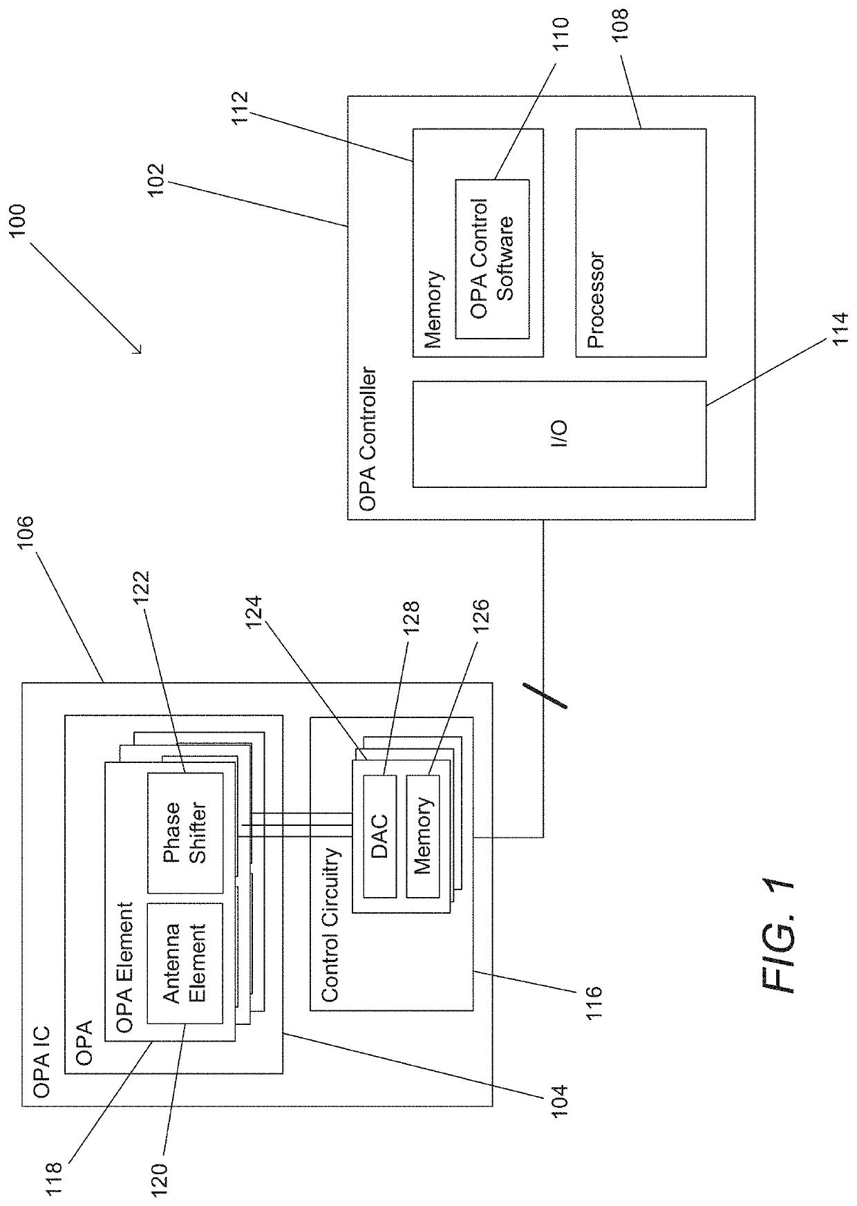
[0052]Turning now to the drawings, optical systems and processes for controlling and / or calibrating optical systems in accordance with various embodiments of the invention are illustrated. In many embodiments, the optical system includes an OPA and utilizes calibration phase state information to perform functions including (but not limited to) beamforming, focusing, and / or other waveform manipulation and control functions. Processes in accordance with various embodiments of the invention can be utilized to determine phase state calibration information for optical systems including (but not limited to) optical systems that include OPA transmitters (TXs) or OPA receivers (RXs).

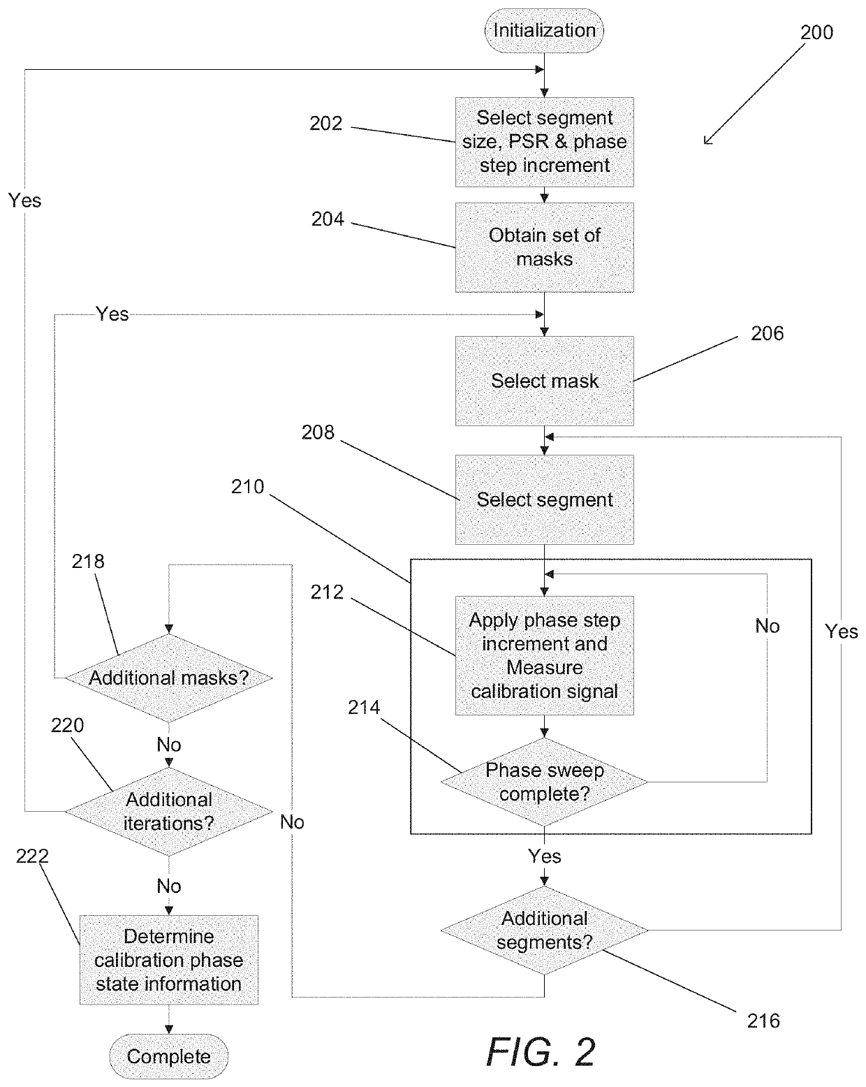
[0053]In several embodiments, the calibration process applies phase sweeps to groups of phase shifters within an OPA and observes changes in one or more calibration signals. In the case of an OPA TX, the calibration signal can be generated by a sensor positioned in a known location relative to the OPA. In the ca...


PUM

PropertyMeasurementUnit
path lengthaaaaaaaaaa
phaseaaaaaaaaaa

Abstract

Optical systems and processes for calibrating and focusing optical systems are described. One embodiment of the invention includes an optical phase array (OPA) and an OPA controller that generates control signals to control phase shifters in the OPA. The OPA controller can calibrate the OPA by performing a plurality of phase sweeps using each of a plurality of different basis masks. Each phase sweep can involve performing a phase sweep across a phase sweep range at a plurality of phase step increments with respect to a first group of phase shifters identified in a basis mask. During the phase sweep, a calibration signal can be measured at each of the plurality of phase step increments and the measurements used to generate calibration phase state information. The calibration phase state information can be utilized to perform functions including (but not limited to) beamforming, focusing, and / or other waveform manipulation and control functions.

Description

CROSS-REFERENCE TO RELATED APPLICATIONS[0001]The current application claims priority to U.S. Provisional Patent Application No. 62 / 781,541, entitled “Fast and Efficient Phase Control and Calibration for Optical Phased Arrays” and filed Dec. 18, 2018, the disclosure of which is incorporated herein by reference in its entirety.FIELD OF THE INVENTION[0002]The present invention relates generally to optical phased arrays and more specifically to calibration processes for optical phased arrays that incorporate controllable phase shifters.BACKGROUND[0003]Optical Phased Arrays (OPA) are becoming a prominent component of a large number of optical systems utilized in a broad range of applications including (but not limited to) LiDAR, sensing, imaging, projection, and communications. OPAs are typically constructed from an array of elements designed to either transmit optical signals or receive impinging light. The relative timing and amplitude of the signal transmitted in an OPA transmitter (T...

Claims


Application Information

Patent Timeline
Patent Type & Authority Applications(United States)
IPC IPC(8): G02F1/29G02B6/293
CPCG02F1/292G02B6/29395G02B6/29313G01R25/005
Inventor HAJIMIRI, SEYED ALI
Owner CALIFORNIA INST OF TECH
Why Eureka
Try Eureka