Filter and operating method thereof

a filter and filter technology, applied in the field of filters, to achieve the effect of accurate filter signal output function

Active Publication Date: 2020-06-25
UPI SEMICON CORP
View PDF3 Cites 0 Cited by
  • Summary
  • Abstract
  • Description
  • Claims
  • Application Information

AI Technical Summary

Benefits of technology

[0004]The present invention provides a filter and an operating method thereof, which may effectively reduce a change broug

Problems solved by technology

In view of this, how to reduce an equivalent resistance value change brought by a manufacturing procedure a

Method used


Image

  • Filter and operating method thereof
  • Filter and operating method thereof
  • Filter and operating method thereof

Examples


Embodiment Construction

[0024]In order to make the content of the present invention more comprehensible, embodiments are described below as examples of implementation of the present invention. Wherever possible, the same reference numbers are used in the drawings and the description to refer to the same or like parts, components or steps.

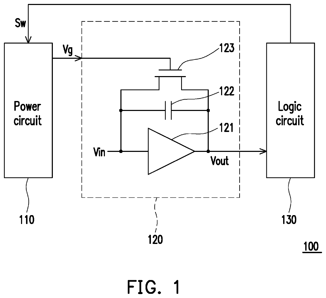
[0025]FIG. 1 is a circuit schematic diagram of a filter according to an embodiment of the present invention. Referring to FIG. 1, the filter 100 includes a power circuit 110, a filter circuit 120 and a logic circuit 130. The filter circuit 120 includes an amplifier 121, a capacitor 122 and a transistor 123. An output end of the amplifier 121 is coupled to the logic circuit 130. A first end of the transistor 123 is coupled to the output end of the amplifier 121, and a second end of the transistor 123 is coupled to an input end of the amplifier 121. A first end of the capacitor 122 is coupled to the output end of the amplifier 121, and a second end of the capacitor 122 is co...


PUM


Abstract

A filter and an operating method thereof are provided. The filter includes a logic circuit, a power circuit and a filter circuit. The logic circuit provides a switching control signal. The power circuit is coupled to the logic circuit. The filter circuit is coupled to the power circuit and the logic circuit. The filter circuit includes an amplifier, a first capacitor and a first transistor. An output end of the amplifier is coupled to the logic circuit, and provides an output signal. The first capacitor is coupled between an input end and output end of the amplifier. The first transistor is connected in parallel with the first capacitor. A control end of the first transistor is coupled to the power circuit. The logic circuit provides a switching control signal to the power circuit according to the output signal. The power circuit supplies a control voltage to the first transistor according to the switching control signal. Therefore, the filter of the present invention and its method of operation can provide an accurate filtered signal output function.

Description

CROSS-REFERENCE TO RELATED APPLICATION[0001]This application claims the priority benefit of China application serial no. 201811557626.7, filed on Dec. 19, 2018. The entirety of the above-mentioned patent application is hereby incorporated by reference herein and made a part of this specification.BACKGROUND OF THE INVENTION1. Field of the Invention[0002]The present invention generally relates to a circuit, in particular, to a filter and an operating method thereof.2. Description of Related Art[0003]In a circuit architecture of an existing filter, a transistor may usually be applied to the circuit architecture of the filter as a pseudo-resistor due to a specific operation characteristic thereof. However, since a threshold voltage Vth of a transistor may change with a temperature or a manufacturing procedure to correspondingly change a current flowing through the transistor, equivalent resistance value of the transistor is likely to change with the temperature to generate a great offse...

Claims


Application Information

Patent Timeline
IPC IPC(8): H03H19/00H03F3/19H03F3/45H03K17/687
CPCH03H19/004H03F3/19H03F3/45179H03K17/687H03H11/54H03F3/195H03F3/45475H03F2203/45514H03F2203/45544H03H11/12H03H11/1282
Inventor HUANG, CHAO-CHUNGKUO, KUO-JENJAN, YI-XIAN
Owner UPI SEMICON CORP
Why Eureka
Try Eureka