
Method for forming semiconductor pattern

a semiconductor and pattern technology, applied in the field of semiconductor processing, can solve current loss, and problems such as problems such as short channel effects, and achieve the effect of reducing the defect caused by micro-loading effects in the semiconductor process and controlling the size of the holes formed

Active Publication Date: 2020-07-02
UNITED MICROELECTRONICS CORP
View PDF0 Cites 0 Cited by
  • Summary
  • Abstract
  • Description
  • Claims
  • Application Information

AI Technical Summary

Benefits of technology

This approach effectively reduces defects caused by micro-loading effects, ensuring complete etching of contact holes and enhancing the conductivity of subsequently formed contact structures.

Problems solved by technology

However, others issues may be happened, such as short channel effects, the on current loss and other problems.

Method used


Image

  • Method for forming semiconductor pattern
  • Method for forming semiconductor pattern
  • Method for forming semiconductor pattern

Examples


Embodiment Construction

[0014]To provide a better understanding of the present invention to users skilled in the technology of the present invention, preferred embodiments are detailed as follows. The preferred embodiments of the present invention are illustrated in the accompanying drawings with numbered elements to clarify the contents and the effects to be achieved.

[0015]Please note that the figures are only for illustration and the figures may not be to scale. The scale may be further modified according to different design considerations. When referring to the words “up” or “down” that describe the relationship between components in the text, it is well known in the art and should be clearly understood that these words refer to relative positions that can be inverted to obtain a similar structure, and these structures should therefore not be precluded from the scope of the claims in the present invention.

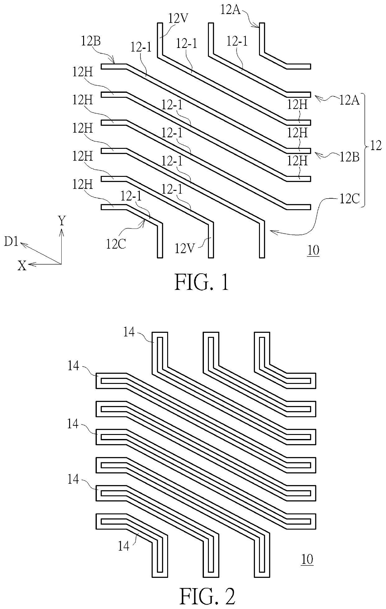
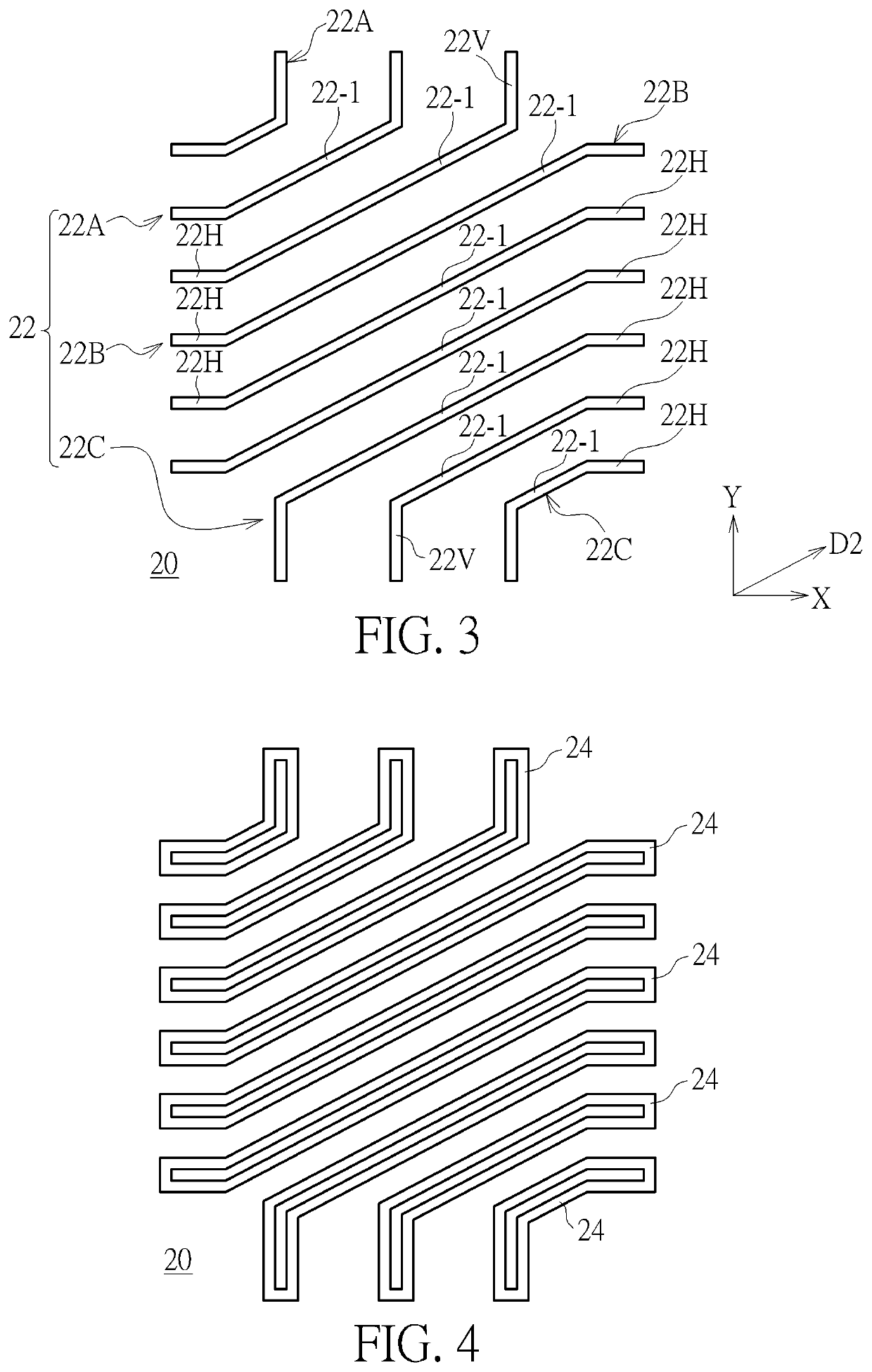
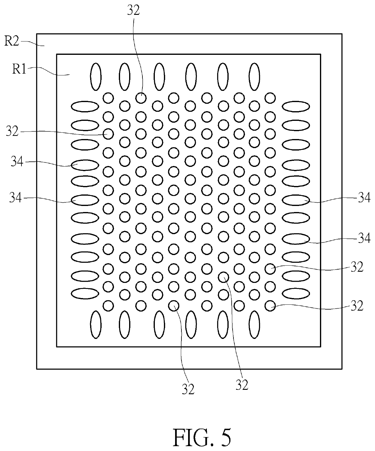
[0016]As shown in FIG. 1 to FIG. 5, FIG. 1 is a top view of a first pattern of the present inventio...


PUM

PropertyMeasurementUnit
thicknessaaaaaaaaaa
thicknessaaaaaaaaaa
thicknessaaaaaaaaaa

Abstract

The present invention provides a method for forming a semiconductor pattern, comprising: firstly, a target layer is provided and a first material layer is formed on the target layer, and then a first pattern is formed on the first material layer, followed by a first self-aligned double pattering step is performed, a plurality of first grooves are formed in the first material layer. Next, a second material layer is formed on the first material layer, and a plurality of second grooves are formed in the second material layer. Next, transferring a pattern of the overlapping portion of the first grooves and the second grooves into the target layer, the target layer includes a plurality of third patterns and a plurality of fourth patterns, an area of each fourth pattern is larger than an area of each third pattern.

Description

BACKGROUND OF THE INVENTION1. Field of the Invention[0001]The present invention relates to the field of semiconductor processing, and more particularly to a method of forming a semiconductor pattern capable of reducing micro-loading effects.2. Description of the Prior Art[0002]Dynamic random access memory (DRAM) is a kind of volatile memory, which is constituted by a plurality of memory cells. Each memory cell is mainly constituted by one transistor and one capacitor controlled by a transistor, and each memory cell are electrically connected by the word line (WL) and bit line (BL).[0003]In order to improve the operation speed of the dynamic random access memory, and to meet consumer demand for miniaturization of electronic devices, the channel length of the transistor of the dynamic random access memory needs to be shorten. However, others issues may be happened, such as short channel effects, the on current loss and other problems.[0004]Accordingly, in order to overcome the above p...

Claims


Application Information

Patent Timeline
Patent Type & Authority Applications(United States)
IPC IPC(8): H01L27/108H10B12/00
CPCH01L27/10897H01L27/10876H01L27/10823H10B12/02H10B12/09H01L21/31144H01L21/0337H01L21/31111H10B12/053H10B12/34H10B12/50
Inventor LIN, GANG-YITZOU, SHIH-FANGLEE, FU-CHECHANG, FENG-YILIN, YING-CHIHHUANG, KAI-LOUCHANG, YI-CHING
Owner UNITED MICROELECTRONICS CORP
Learn More