Vertical Lift Single Engine Vehicle System

a single engine, vertical lift technology, applied in vertical landing/take-off aircrafts, aircraft navigation control, fuel systems for specific fuels, etc., can solve the problems of inefficient lift, high cost, heavy, complicated, etc., to increase the lift, reduce the drag, and increase the structural integrity of the fuselage

Active Publication Date: 2020-07-16
MILLER CURTIS
View PDF9 Cites 1 Cited by
  • Summary
  • Abstract
  • Description
  • Claims
  • Application Information

AI Technical Summary

Benefits of technology

[0016]The engine design in the present system can be a hybrid between a turbo fan jet and a ramjet. Ramjets are simple but only become efficient at high speeds, while turbo fan jets are efficient at lower speeds but are much more complicated. The present design has characteristics of ramjet but provides static thrust when vehicle is not moving. A lower part of the air stream from the propeller provides high speed air into intake ducts that compress when combined together in the main combustion chamber where combustion can occur. A second stage of the duct system can provide additional side intake ducts for more air and compression in the main combustion chamber. Finally, a third stage of the duct system can provide additional side intake ducts for additional air and cooling. The duct system can include an exit nozzle providing variable outlet / directional thrust vectoring.
[0017]The present system has a unique wing design. The wing can be comprised of polycarbonate and carbon fiber sandwich panels, wherein the design can be uncomplicated yet allows for the wing to be thin, flexible, and mobile (e.g., change shape) in flight. For example, the wing can be highly curved at low speed for increased lift, and flatter at high speed for less drag.
[0018]Fuselage design of the present system is advantageous. The sides of the aircraft fuselage can be strong carbon fiber sandwich flat panels. A panel on each side of the fuselage provides the system's load bearing similar to load bearing walls. In order to connect additional items to the system structure, a cross bar connecting the two sides can be installed to provide a mounting surface, which also adds additional structural integrity to the fuselage. The top half can be a traditional frame design that is covered with polycarbonate windows and connects to lower fuselage.
[0019]The present system allows for a vertical take-off and landing (VTOL) that would qualify for FAA sport pilot designation. An upper half of the propeller generates high speed air that sends air over the rear wing creating lift even when aircraft is not moving. In addition, the upper half of the propeller loads air over the elevons in the wing such that control surfaces can be functional even when the aircraft is not moving. A lower half of the propeller can provide air for new engine design to provide lift to front of vehicle system. The lower half of the propeller air can load the rudders even when the vehicle is not moving so they are functional at all times. The vehicle system can have a small number of control surfaces and smaller wing size providing a much smaller drag profile.
[0020]An advantage of the present system is its efficient design, light weight, ease to manufacture, and ability to operate at various speeds.
[0021]A further advantage of the present vehicle system is that it is an efficient single engine VTOL that runs on propane, hydrogen, natural gas, and / or ammonia, resulting in an inexpensive and cleaner burning than gasoline.

Problems solved by technology

However, such configuration prevents the aircraft from tilting its rotor for axial flow in horizontal flight with left developed by a fixed wing.
Therefore, it must rely on the rotor's inefficient lift in edgewise airflow with only enough rotor clearance available for a slight tilt to develop some horizontal speed.
Conventional engines used for aircrafts are expensive, complex, heavy, designed only for a specific speed.
Moreover, such engines generate larges amount of greenhouse gases.

Method used


Image

  • Vertical Lift Single Engine Vehicle System
  • Vertical Lift Single Engine Vehicle System
  • Vertical Lift Single Engine Vehicle System

Examples


Embodiment Construction

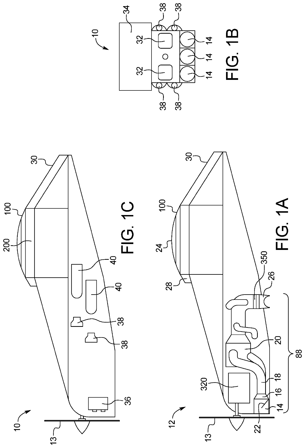
[0034]The present vertical lift vehicle system 10 having a single internal combustion engine fueled by propane can meet FAA regulations for ultralight, sport pilot, and certified aircrafts. The present vehicle system 10 is designed for subsonic, trans-sonic, and supersonic speeds. The present aircraft can include one to four seats arranged in any suitable matter, including two by two seats and / or one seat behind another seat. Of course, additional seats are contemplated. A single engine can control a single vertically mounted propeller, wherein the propeller can be large enough (e.g., approximately 50 to 60 inches long) to provide a large air stream.

[0035]The present system includes a fuselage body with a front propeller. The air stream from the propeller 13 is split into an upper half air stream and a lower half air stream. The upper half air stream is directed uninterrupted to a high lift thin airfoil 100 attached above the top surface 200 of the vehicle fuselage body towards the ...


PUM


Abstract

The present vertical lift vehicle system can include a single internal combustion engine, a single propeller, and a plurality of small ducts. The small ducts can connect to a single main duct acting as a combustion chamber, wherein the combustion chamber combines air from the small ducts with propane, wherein when ignited the contents of the main duct produce added thrust to the vehicle as it exits the main duct.

Description

CROSS-REFERENCE TO RELATED APPLICATIONS[0001]This application incorporates by reference and claims the benefit of priority to U.S. Provisional Application 62 / 918,122 filed on Jan. 15, 2019.BACKGROUND OF THE INVENTION[0002]The present subject matter relates generally to vertical lift aircrafts.[0003]Various systems exist for autonomously piloted aerial vehicles that are able to take off, loiter, and land without the use of a runway. Vertical takeoff and landing (VTOL) vehicles address this limitation and may come in various forms of hand-launched aerial vehicles having a main wing and a vertical / horizontal tail control surfaces, or three or four rotor propellers that are operable to take off and land vertically. Aerial vehicles having a main wing and a vertical / horizontal tail control surfaces tend to be more efficient and faster on route, while rotor copters are less efficient in forward flight but have takeoff and landing advantages.[0004]Conventional single rotor helicopters have ...

Claims


Application Information

Patent Timeline
Patent Type & Authority Applications(United States)
IPC IPC(8): B64C29/00B64D37/30
CPCB64C29/0025B64D37/30B64C29/0066B64C15/02B64D27/20F05D2220/90F02K1/002F02K1/12F02C6/206F02K3/10
Inventor MILLER, CURTIS
Owner MILLER CURTIS
Why Eureka
Try Eureka