Systems and Methods for Quick Dissipation of Stored Energy from Input Capacitors of Power Inverters

Active Publication Date: 2020-07-23
NEWLIGHT CAPITAL LLC
View PDF0 Cites 3 Cited by
  • Summary
  • Abstract
  • Description
  • Claims
  • Application Information

AI Technical Summary

Benefits of technology

[0006]One embodiment of the disclosure is drawn to a photovoltaic system connected to an inverter having an input capacitor. The photovoltaic system includes at least one photovoltaic module and a maximum power point tracking (MPPT) controller coupled between the input capacitor of the inverter and the at least one photovoltaic module. The MPPT controller includes a direct current (DC) converter configured to reduce, in a forward buck mode, a voltage of the at least one photovoltaic module, to supply power from the at least one photovoltaic module to the input capacitor of the inverter.
[0007]The photovoltaic system also includes a microcontroller unit (MCU) configured to control the DC converter to allow the at least one photovoltaic module to operate at a maximum power point. The DC converter is software-configurable to increase, in a reverse boost mode, a voltage of the input capacitor of the inverter, to dissipate power from the input capacitor in the at least one photovoltaic module, and the MPPT controller is configured to, based upon one or more triggers, automatically change the DC converter from the forward buck mode to the reverse boost mode to dissipate energy stored in the input capacitor of the inverter.
[0008]One embodiment of the disclosure is drawn to a system connecting at least one photovoltaic module to an inverter having an input capacitor. The system includes a maximum power point tracking (MPPT) controller coupled between the input capacitor of the inverter and the at least one photovoltaic module. The MPPT controller includes a direct current (DC) converter configured to reduce, in a forward buck mode, a voltage of the at least one photovoltaic module, to supply power from the at least one photovoltaic module to the input capacitor of the inverter.
[0009]The system also includes a microcontroller unit (MCU) configured to control the DC converter to allow the at least one photovoltaic module to operat

Problems solved by technology

In a case of fire or other emergency, when any electrical power generation or distribution system must be shut down quickly, there are known electrical hazards associated with ele

Method used


Image

  • Systems and Methods for Quick Dissipation of Stored Energy from Input Capacitors of Power Inverters
  • Systems and Methods for Quick Dissipation of Stored Energy from Input Capacitors of Power Inverters
  • Systems and Methods for Quick Dissipation of Stored Energy from Input Capacitors of Power Inverters

Examples


Embodiment Construction

[0021]The following descriptions are meant to further clarify the present disclosure by giving specific examples and embodiments. These embodiments are meant to be illustrative rather than exhaustive. The full scope of the disclosure is not limited to any particular embodiment disclosed in this specification, but rather is defined by the dependent claims.

[0022]In view of the above, a system and method that, in the case of an emergency shutdown, shuts down not only the panels, but also provides for a safe and quick dissipation of the energy stored on the input capacitors of the inverter is needed. This renders the solar wiring safe for people to accidentally touch, without any bodily harm.

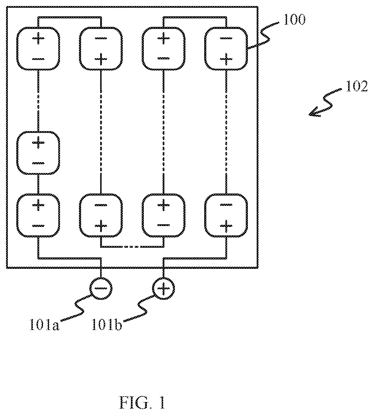
[0023]FIG. 1 is a schematic structural diagram illustrating photovoltaic cells in a photovoltaic module according to some embodiments of the present disclosure.

[0024]A typical photovoltaic (PV) system includes photovoltaic cells 100, or solar cells, which absorb light and convert the energy of the l...


PUM


Abstract

Methods and systems for connecting a photovoltaic module and an inverter having an input capacitor are presented. The photovoltaic system includes a maximum power point tracking (MPPT) controller coupled between the inverter and the photovoltaic module. The MPPT controller includes a direct current (DC) converter configured to reduce, in a forward buck mode, a voltage of the photovoltaic module, to supply power from the photovoltaic module to the input capacitor of the inverter. The photovoltaic system also includes a microcontroller unit (MCU) configured to control the DC converter to allow the photovoltaic module to operate at a maximum power point, and to increase, in a reverse boost mode, a voltage of the input capacitor of the inverter, to dissipate power from the input capacitor in the photovoltaic module, and the MPPT controller is configured to, based upon one or more triggers.

Description

CROSS-REFERENCE TO RELATED APPLICATIONS[0001]The present application is a continuation application of U.S. patent application Ser. No. 15 / 159,699, filed May 19, 2016, entitled “Systems and Methods for Quick Dissipation of Stored Energy from Input Capacitors of Power Inverters”, which claims the benefit of the filing date of Provisional U.S. Pat. App. Ser. No. 62 / 165,672, filed May 22, 2015, entitled “Systems and Methods for Quick Dissipation of Stored Energy from Input Capacitors of Power Inverters during Emergency Shutdown of Photovoltaic Systems”, the entire disclosures of which applications are hereby incorporated herein by reference.[0002]The present application relates to U.S. Pat. Pub. No. 2014 / 0327313, filed Apr. 23, 2014 and entitled “System and Method for Low-Cost, High-Efficiency Solar Panel Power Feed,” which claims the benefit of the filing date of Provisional U.S. Patent Application Ser. No. 61 / 818,036, filed May 1, 2013 and entitled “System and Method for Low-Cost, Hig...

Claims


Application Information

Patent Timeline
IPC IPC(8): H02J3/38H02M3/158H02M1/32
CPCY02E10/563Y02E10/58H02M2001/322H02J3/38H02M3/1582G05F1/67H02M3/1588H02M1/32H02H7/20H02J2300/26H02J3/381Y02B70/10H02M1/322Y02E10/56
Inventor EIZIPS, DANIELAVRUTSKY, MORDECHAYKONDRASHOV, SERGEY
Owner NEWLIGHT CAPITAL LLC
Why Eureka
Try Eureka