Test probe assembly and test socket

a test probe and assembly technology, applied in the direction of instruments, measurement devices, instrument screening arrangements, etc., can solve the problems of noise leakage between the signal probes, the whole test socket has to be replaced, and the difficulty of such a convention method to support the probes, so as to reduce the repair cost, minimize exposure, and improve the noise shield performance

Active Publication Date: 2020-07-30
LEENO INDAL
View PDF3 Cites 3 Cited by
  • Summary
  • Abstract
  • Description
  • Claims
  • Application Information

AI Technical Summary

Benefits of technology

[0018]First, the probe hole is covered with the metal pipe as much as possible, thereby minimizing exposure between the signal probes and improving noise-shield performance.
[0019]Second, only a damaged test probe assembly is replaceable in the test socket, thereby reducing repair costs.
[0020]Third, the probe supporting member is firmly supported in the metal pipe, thereby improving durability.
[0021]Fourth, it is easy to manufacture the test probe assembly for a shield against noise.

Problems solved by technology

However, it is difficult for such a convention method to support the probes when the insulation support plate is not thick enough to support the probes.
On the other hand, when the insulation support plate is thick, the support plate causes a problem of noise leakage between the signal probes.
Such a conventional method has a problem that the whole test socket has to be replaced even when only one test probe is damaged among the test probes mounted to the test socket.
Further, the conventional method has a problem that it is very inconvenient and hard to insert the epoxy insulator in the probe hole of the test socket.
In particular, the conventional method has a problem that the epoxy insulator inserted in the probe hole of the test socket is not easily supported and thus sticks out.

Method used


Image

  • Test probe assembly and test socket
  • Test probe assembly and test socket
  • Test probe assembly and test socket

Examples


first embodiment

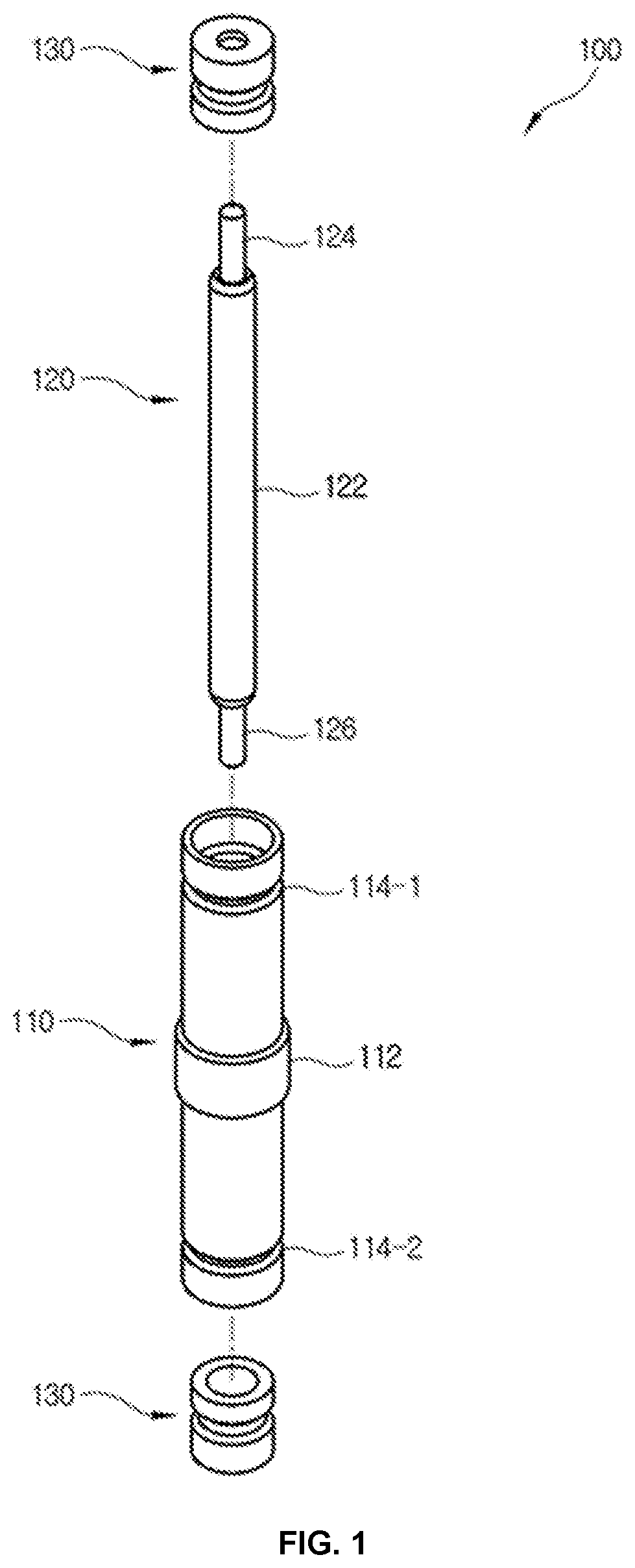
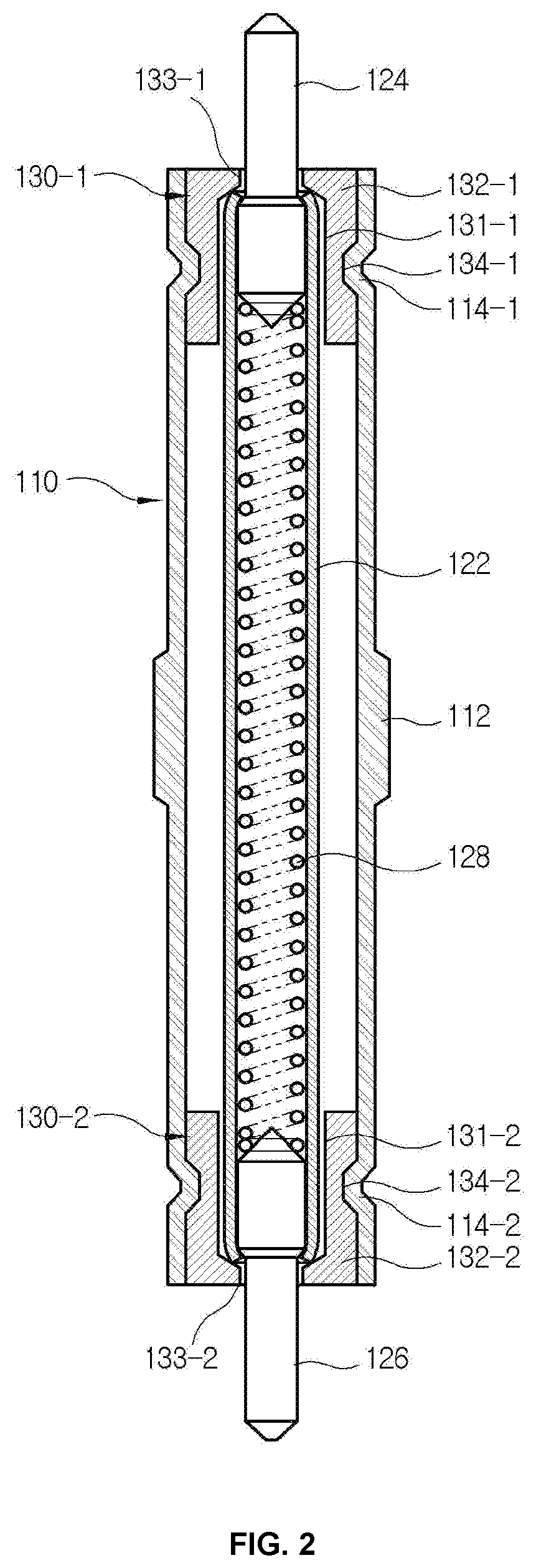
[0031]FIGS. 1 and 2 are respectively a perspective view and a cross-section view of a test probe assembly 100 according to the present disclosure. As shown therein, the test probe assembly 100 includes a conductive pipe 110, a probe 120 accommodated in the pipe 110, and an insulation probe supporting member 130 supporting the probe 120 in the pipe 110.

[0032]The conductive pipe 110 is manufactured as a hollow pipe made of metal, for example, iron, copper, aluminum, beryllium copper, or alloy thereof, or the like. The conductive pipe 110 includes a flange 112 radially extended in a middle of an outer surface thereof, and first and second projections 114-1 and 114-2 circumferentially protruding inward by rolling work at opposite ends thereof. The first and second projections 114-1 and 114-2 are respectively accommodated in first and second projection accommodator 134-1 and 134-2 of the probe supporting member 130 to be described later. Here, the rolling work is carried out with the pro...

sixth embodiment

[0055]FIG. 10 illustrates a probe supporting member 130 of a test probe assembly 100 according to the present disclosure.

[0056]A probe supporting member 130 includes a pipe insertion portion 132 to be inserted in the pipe 110 at opposite end portions thereof, a projection accommodator 134 formed on an outer circumferential surface of the pipe insertion portion 132, and a flange 136 radially extended from the pipe insertion portion 132.

[0057]The probe supporting member 130 includes a barrel hole 131 corresponding to an outer diameter of a barrel 122 of the probe 120, and a plunger hole 133 corresponding to outer diameters of plungers 124 and 126.

[0058]In FIG. 10, the plunger hole 133 passes by a flange 136 and deeply extended up to the pipe insertion portion 132. In this case, the projection accommodator 134 is formed in the pipe insertion portion 132 at a position to surround the plunger hole 133. Since the pipe insertion portion 132 surrounding the plunger hole 133 is thicker than ...

seventh embodiment

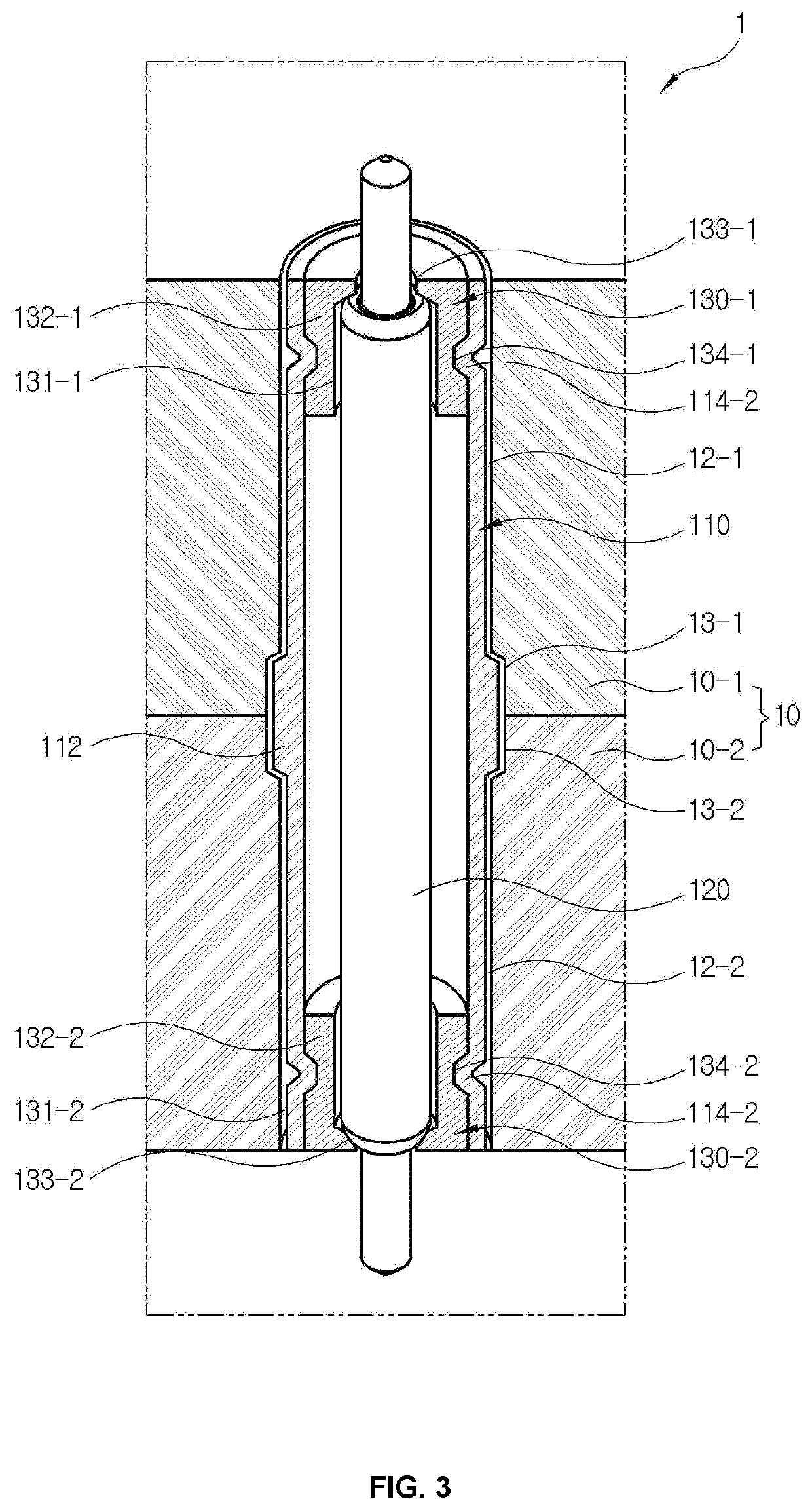
[0059]FIG. 11 is an exploded perspective view of a test probe assembly according to the present disclosure, and FIG. 12 is a partial cross-section view of a test socket to which the test probe assembly of FIG. 11 is applied.

[0060]As shown therein, the test probe assembly 100 includes a conductive first pipe 110-1, a conductive second pipe 110-2, a probe 120 retractable up and down as accommodated in the first and second pipes 110-1 and 110-2, and insulation first and second probe supporting members 130-1 and 130-2 for supporting the probe within the first and second pipes 110-1 and 110-2. In this test probe assembly 100, the probe 120 and the first and second probe supporting members 130-1 and 130-2 except the first and second pipes 110-1 and 110-2 have the same structure as the probe 120 and the first and second probe supporting members of the first embodiment shown in FIGS. 1 to 3, and thus repetitive descriptions thereof will be avoided.

[0061]The first pipe 110-1 includes a first...


PUM


Abstract

A test probe assembly includes: a conductive pipe; a probe inserted in the pipe without contacts and elastically retractable along a lengthwise direction; and an insulation probe supporting member configured to support the probe between an inner wall of the pipe and an outer surface of the probe. The test probe assembly of the present disclosure is improved in noise shield performance and convenient in repairing the probe since the probe is mounted to a probe socket as supported in a metal pipe without contacts.

Description

REFERENCE TO RELATED APPLICATIONS[0001]This is a continuation of pending International Patent Application PCT / KR2018 / 007343 filed on Jun. 28, 2018, which designates the United States and claims priority of Korean Patent Application No. 10-2017-0147488 filed on Nov. 7, 2017, and Korean Patent Application No. 10-2018-0067907 filed on Jun. 14, 2018, the entire contents of which are incorporated herein by reference.FIELD OF THE INVENTION[0002]The present disclosure relates to a test probe assembly and a test socket for testing a radio-frequency or high-speed semiconductor or the like object to be tested.BACKGROUND OF THE INVENTION[0003]In a test socket for testing a radio-frequency or high-speed semiconductor, a signal probe is mounted to a conductive block without contact for a shield against noise from an adjacent signal probe. In this case, the signal probe includes opposite end portions supported on insulation support plates arranged on both sides of the conductive block after the s...

Claims


Application Information

Patent Timeline
Patent Type & Authority Applications(United States)
IPC IPC(8): G01R1/067G01R1/18G01R3/00
CPCG01R3/00G01R1/06722G01R1/06733G01R1/18G01R1/06772G01R1/0466G01R1/045G01R1/0441G01R31/2886
Inventor JEONG, JAE-HWANKIM, GEUN-SUSHIN, JUNG-CHUL
Owner LEENO INDAL
Why Eureka
Try Eureka