
Insert for hot isostatic pressing treatment

a technology of inserting and isostatic pressing, which is applied in the direction of crystal growth process, after-treatment details, machines/engines, etc., can solve the problems of micro-voids in the crystal blade, cracks within the component, and greater regions, so as to reduce the damage to the blade and reliable treatment method

Active Publication Date: 2020-08-06
ROLLS ROYCE PLC +1
View PDF0 Cites 0 Cited by
  • Summary
  • Abstract
  • Description
  • Claims
  • Application Information

AI Technical Summary

Benefits of technology

The patent text explains that using a special tool to hold blades can prevent damage caused by recrystallization of contact regions, which means that the blades can be reused without having to be thrown away. This also ensures that all components are processed equally, which results in better reproducibility between different batches and treats the components in a more reliable way.

Problems solved by technology

An issue, however, arises with the casting process in that micro-voids can be formed in the crystal blades.
When the blades are in operation repeated exposure to the thermal and operational conditions of the engine can result in creep, which is a deformation of an area of the blade resulting from the strain and temperature which the components are under.
Any creep around the micro-void regions can be greater than in the surrounding areas, and as such can lead to cracks within the component.
This random distribution of blades, however, can lead to some of the blades being positioned poorly and even touching neighbouring blades or the basket.
This contact between the components is one of the issues of the current HIP treatment, as any point of contact on the blades leads to localised damage resulting from re-crystallisation in the area where contact was present.
This damaged region means that some of the blades have to be reworked or scrapped.

Method used


Image

  • Insert for hot isostatic pressing treatment
  • Insert for hot isostatic pressing treatment

Examples


Embodiment Construction

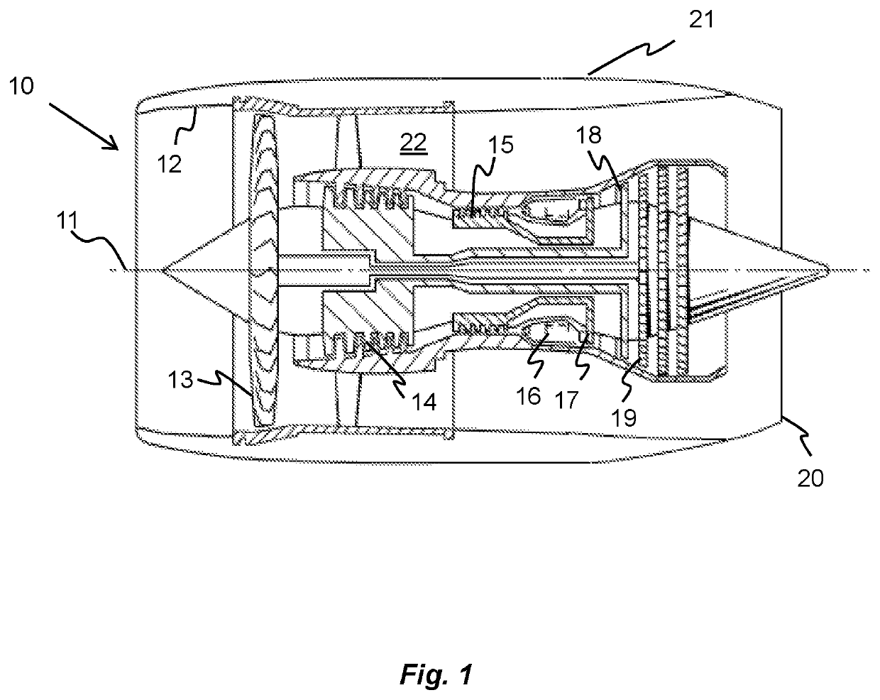
[0026]With reference to FIG. 1, a gas turbine engine is generally indicated at 10, having a principal and rotational axis 11. The engine 10 comprises, in axial flow series, an air intake 12, a propulsive fan 13, an intermediate pressure compressor 14, a high-pressure compressor 15, combustion equipment 16, a high-pressure turbine 17, an intermediate pressure turbine 18, a low-pressure turbine 19 and an exhaust nozzle 20. A nacelle 21 generally surrounds the engine 10 and defines both the intake 12 and the exhaust nozzle 20. The gas turbine engine 10 works in the conventional manner so that air entering the intake 12 is accelerated by the fan 13 to produce two air flows: a first air flow into the intermediate pressure compressor 14 and a second air flow which passes through a bypass duct 22 to provide propulsive thrust. The intermediate pressure compressor 14 compresses the air flow directed into it before delivering that air to the high pressure compressor 15 where further compressi...


PUM

PropertyMeasurementUnit
pressuresaaaaaaaaaa
pressureaaaaaaaaaa
pressuresaaaaaaaaaa

Abstract

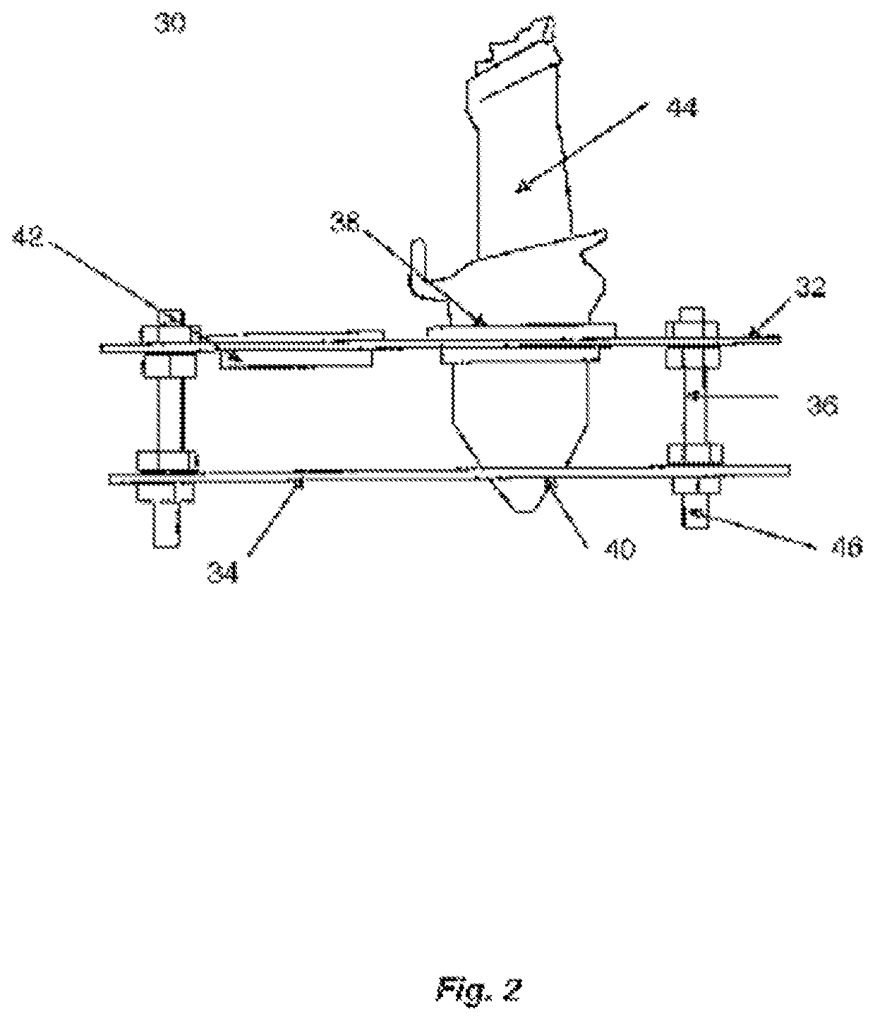
An insert fixture for use in the manufacture of a single crystal component by a hot isostatic pressing process. The insert fixture comprising: at least a lower plate separated from an upper plate by interconnecting members. The upper plate comprises at least a slot for the insertion of the single crystal component. The lower plate features a related engagement feature for engaging with the single crystal component. The insert fixture may be cast from a ceramic material. The insert fixture may be cast from an alumina ceramic or molybdenum alloy. The interconnecting members may be made from a molybdenum alloy.

Description

CROSS-REFERENCE TO RELATED APPLICATIONS[0001]This specification is based upon and claims the benefit of priority from United Kingdom patent application number GB 1901611.2 filed on Feb. 6 2019, the entire contents of which are incorporated herein by reference.BACKGROUNDField of the Disclosure[0002]The present disclosure concerns an insert for supporting components during hot isostatic pressing (HIP).Description of the Related Art[0003]Turbine blades and vanes used in gas turbine engines can be manufactured as single crystal structures. The materials for these are typically nickel or cobalt based superalloys, which can be cast to form the desired shape with a single crystal structure. The use of such materials allows the blades to withstand the forces and temperatures in the engine for prolonged periods of time. An issue, however, arises with the casting process in that micro-voids can be formed in the crystal blades. When the blades are in operation repeated exposure to the thermal ...

Claims


Application Information

Patent Timeline
Patent Type & Authority Applications(United States)
IPC IPC(8): C30B33/02F01D5/14C22F1/00
CPCF05D2230/42C22F1/008F01D5/14F05D2220/30F05D2300/701C30B33/02F01D5/286F05D2300/607C30B35/002
Inventor BIERNOT, FELIXNIKOLOV, TOMA DPATEL, PRIYESH RTSANG, JUSTIN P M
Owner ROLLS ROYCE PLC
Learn More