
Thermal fracture and microcarbon separation of coal particles

a technology of thermal fracture and coal particles, applied in the direction of carbon preparation/purification, direct heating destructive distillation, carbon preparation/purification, etc., can solve the problems of no effective way to separate carbon type, no effective way to reduce solid particle size, etc., to achieve rapid or instantaneous thermal fracturing of coal, rapid reduction of coal particle size, and reduction of total carbon mass

Active Publication Date: 2020-08-20
FENIX ADVANCED TECH LTD
View PDF0 Cites 0 Cited by
  • Summary
  • Abstract
  • Description
  • Claims
  • Application Information

AI Technical Summary

Benefits of technology

The patent describes a new way to quickly break down coal into smaller particles using a process called thermal fracturing. This method can separate volatile matter from the coal without reducing the amount of carbon in the volatile matter. It can also remove impurities like sulfur, nitrogen, and phosphorous. The process involves heating the coal in an oxygen-depleted gas at high temperatures. The temperature range can produce different types of coal particles, including microcarbon particles. The process can save the carbon in the coal as a solid, which has advantages for transportation and handling. The resulting products are unique and have significant value.

Problems solved by technology

Most coal tar is likely produced via destructive distillation.
None of these methods uses heat to reduce particle size, and none of the methods separate particles by chemical composition or carbon type.
There is currently no effective way to reduce solid particle size and separate carbon type using heat.
Generally, lignite, sub-bituminous coal, and anthracite cannot be used to make coke or are used as a very small amount of the coal blend used to make coke.
Destructive distillation continues in the melt, causing more material to enter the vapor phase, leaving behind voids and pores in the softened viscous mass.
In the solid phase, further destructive distillation occurs, and then carbonization proceeds.
There is still a large amount of volatile matter in the fused coal at this point.
Destructive distillation continues as temperature goes from 600° C. to 1100° C., resulting in further loss in mass consisting of evolved gasses more than just coal tar.
These processes are inefficient and costly.

Method used


Image

  • Thermal fracture and microcarbon separation of coal particles
  • Thermal fracture and microcarbon separation of coal particles
  • Thermal fracture and microcarbon separation of coal particles

Examples


example 1

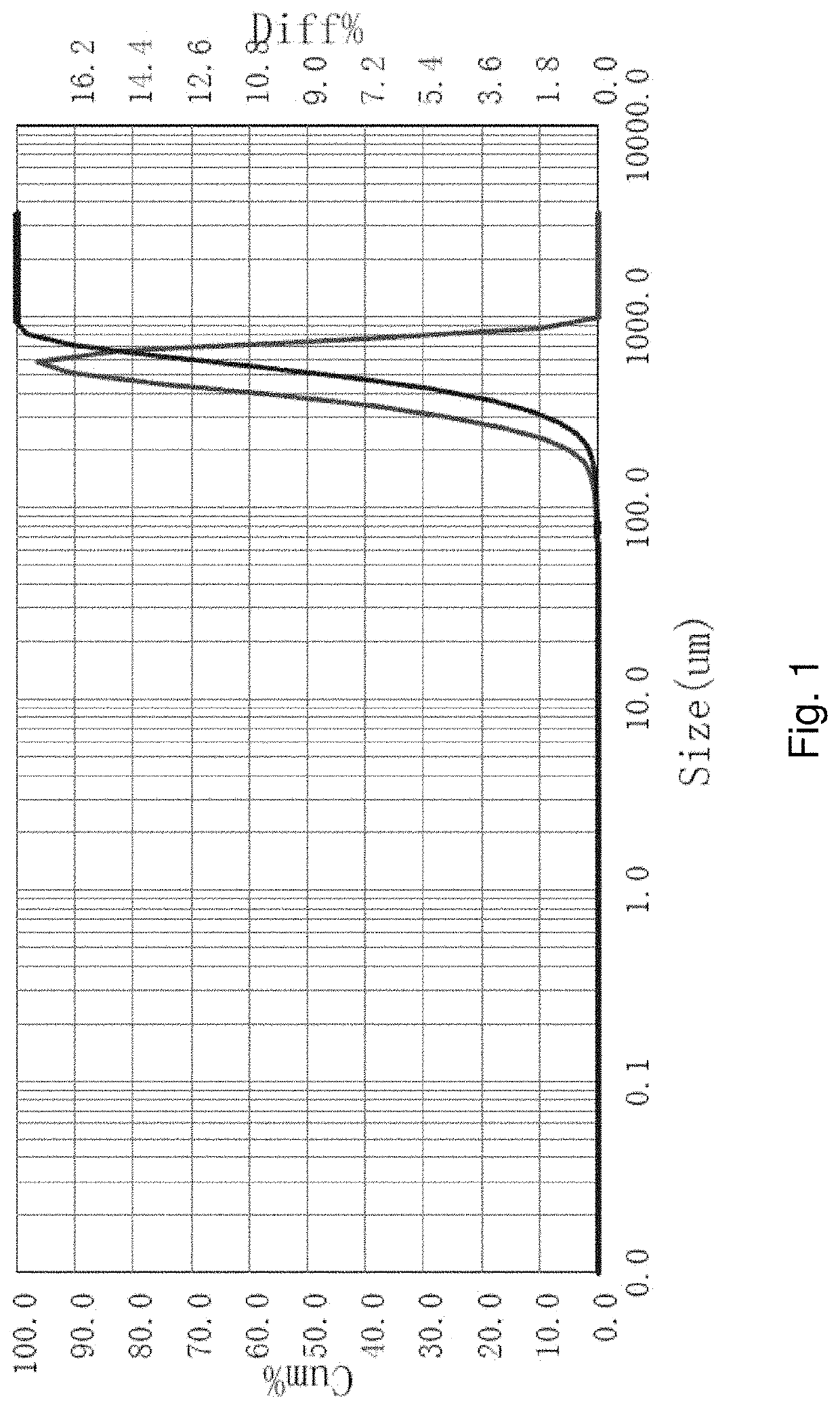
[0064]Sieve analysis was done on the coal particle feed material. Particle size analysis was also done on the material. More than 99% of the mass of the material was greater than 0.355 mm. The material is mixed for a short period 5 seconds with a handheld high-speed mixer in the presence of a non-ionic surfactant to ensure all the particles are separated. Particle size analysis was conducted using a laser diffraction particle size analyzer. The particles have a peak particle size at about 0.5 mm. The average is 0.51 mm with a d97 of 0.795 mm. d97 means that 97% of the particles have a diameter smaller than the size given. The sieve analysis results are reported in Table 1 and the results from the particle size analyzer are shown in FIG. 1.

TABLE 1Retained onMass Sieve +Mass Mass Sieve (mm)Material (g)Sieve (g)Material (g)wt. %1.180419.16416.043.121.481.000418.08395.4022.6810.770.600504.40386.81117.5955.840.500410.04366.4843.5620.680.355371.61349.4322.1810.530.250338.62337.870.750.360...

example 2

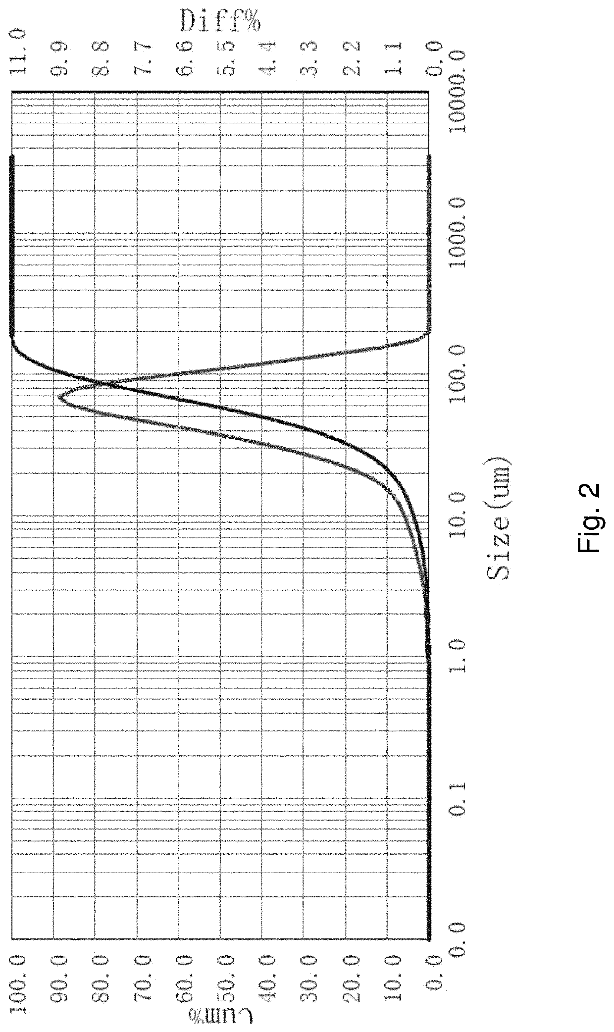
[0065]Sieve analysis was done on the low volatile matter and fractured particles. About 70% of the mass of the material was less than 0.5 mm. In order to get a better understanding of the fractured particle size, particle size analysis was also done on the material using a laser diffraction particle size analyzer. The material was mixed for 10 second with a high-speed hand mixer in the presence of a non-ionic surfactant to ensure all the particles are separated. The particles have a peak particle size at about 0.06 mm. The average is 0.058 mm with a d97 of 0.135 mm. The sieve analysis results are reported in Table 2 and the results from the particle size analyzer are shown in FIG. 2.

[0066]The individual particles produced via thermal fracture conditions are smaller than the feed particle to the thermal fracture process. The average particle size diameter for the thermal fracture particles was reduced by nearly a factor of 10 in this example.

TABLE 2Retained onMass Sieve +Mass Mass Si...

example 3

[0067]The volatile matter of the feed coal particles was measured to be about 33.7%. The feedstock was Pittsburgh 8 coal. Pittsburgh 8 coal is a high volatile matter metallurgical grade coal, meaning in the coking process, it will soften, swell during coal tar evolution, and then fuse together to form the porous long range coke structure.

[0068]After the Pittsburgh 8 coal is used as the feedstock in the rapid thermal fracture and microcarbon separation process described above, the volatile matter of the fractured coal-derived particles ranged between 6% and 9% by mass using a work zone temperature of 1000° C. and a retention time in the work zone of 0.6 seconds.

[0069]It is believed that the coal feed particles heat up so quickly in the rapid thermal fracture process described herein that the fractured solid particles produced in the process do not pass through a softening stage and fusion step as in the case in the much slower coking process. The fractured particles that remain are s...


PUM

PropertyMeasurementUnit
temperatureaaaaaaaaaa
particle sizeaaaaaaaaaa

Abstract

A process for fracturing and devolatilizing coal particles rapidly exposes coal particles to a high temperature, oxygen-depleted work zone for a sufficient time period to cause volatile matter within the coal particles to vaporize and fracture the coal particles. The work zone has a temperature in the range from 600° C. to 2000° C. The coal particles are exposed to the high temperature, oxygen-depleted work zone for a time period less than 1 seconds, and preferably less than 0.3 second. The vaporized volatile matter is condensed and recovered as microcarbon particles.

Description

CROSS-REFERENCE TO RELATED APPLICATION[0001]This application claims the benefit of U.S. Provisional Application No. 62 / 807,655, filed Feb. 19, 2019, and entitled THERMAL FRACTURE AND MICROCARBON SEPARATION OF COAL PARTICLES. This prior application is incorporated by reference.BACKGROUND OF THE INVENTION[0002]This disclosure relates to rapid thermal fracturing of coal particles. The rapid thermal fracturing also enables a separation of larger particles and smaller particles, including nano-size and molecular-size particles. The resulting coal particles have a substantially reduced average particle size and particle fractions having significantly different carbon (or carbonaceous) and mineral properties.[0003]Traditional coal comminution is done by physical means through various attrition methods. Coal is milled for different end uses, for example pulverized coal injection into coal fired power plants or as an additive to a coking process.[0004]Coal is a natural composite material con...

Claims


Application Information

Patent Timeline
Patent Type & Authority Applications(United States)
IPC IPC(8): C01B32/05C10B49/04C10B53/00B02C19/18
CPCC01B32/05B02C19/186C10B53/00C01P2006/40C01P2004/03C10B49/04C10B53/04C10B49/10C10B57/16C01P2004/60
Inventor SWENSEN, JAMES S.GRUNDER, DOUGLAS E.HODSON, SIMON K.
Owner FENIX ADVANCED TECH LTD
Learn More